
Hardware Style Owner's manual


Chapter 5
Wiring Your Control System
5–5
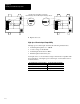
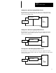
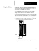
Below is an example of a combination I/O module.
Input and Output Terminals
Connected to Terminal Block
I/O Status Indicators
Terminal Block Release Screw
HSCE
OUT
1
OUT 3
OUT 0
OUT 2
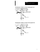
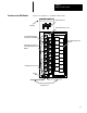
Terminal Block (May Be Color-
coded and Removable on Some
Modules)
Hinged Wiring Terminal Door
with Label
OUTPUT INPUT
Tie Wire
OUT
5
NOT
USED
IN 5
OUT 4
IN 0
AC COM
NOT
USED
NOT
USED
NOT
USED
IN 4
IN 3
IN 2
IN 1
1
2
3
4
5
0
1
2
3
4
5
0
VAC–VDC
Wires Leading to Output
and Input Devices
Color Band
Terminal Block Release Screw
Features of an I/O Module