
Hardware Style Owner's manual


Chapter 2
System Installation Recommendations
2–6
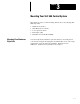
Emergency-Stop Switches
Adhere to the following points concerning emergency–stop switches:
• Do not program emergency–stop switches in the controller program. Any
emergency–stop switch should turn off all machine power by turning off
the master control relay.
• Observe all applicable local codes concerning the placement and labeling
of emergency–stop switches.
• Install emergency–stop switches and the master control relay in your
system. Make certain that relay contacts have a sufficient rating for your
application. Emergency–stop switches must be easy to reach.
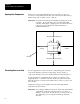
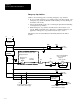
The figure below shows the Master Control Relay Wired in Grounded
System.
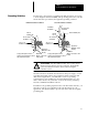
Disconnect
L1 L2
Isolation
Transformer
Fuse
Operation
of either of these contacts will remove
power from the controller external I/O circuits,
stopping machine motion.
MCR
MCR
MCR
Emergency-Stop
Push Button
Overtravel
Limit Switch
Stop
Start
Suppr.
230 V
AC
MCR
(Lo) (Hi)
Incoming Line T
erminals. Connect to
1
15 V
AC terminals of Power Supply
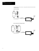
.
DC Power Supply
.
Use N.E.C. Class 2
for UL Listing.
MCR
+
1
15 V
AC
X1
X2
Incoming line terminals. Connect to
24 VDC terminals of Power Supply
.
24 VDC
I/O Circuits
1
15 VAC
I/O Circuits
230 V
AC
I/O Circuits
Master Control Relay (MCR)
Cat. No. 700-PK400A1
Fuse
Fuse
Suppressor
Cat. No. 700-N24