
Hardware Style Owner's manual

Chapter 1
Selecting Your Hardware Components
1–3
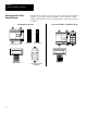
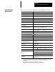
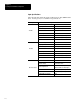
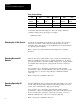
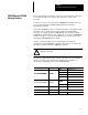
This section provides the specifications for the SLC 500 Fixed Controller.
Description Specification
Memory Type Capacitor-backed RAM memory. Battery back-up optional.
Memory Backup Options EEPROM or UVPROM
Program Memory 1K Instruction Capacity
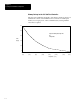
Capacitor Memory Back-up Time Refer to curve on page 1-4.
Battery Life 5 years
Typical Scan Time
➀
8 milliseconds/1K
Bit Execution (XIC) 4 microseconds
Program Scan Hold-up Time after
Loss of Power
20 milliseconds to 700 milliseconds (dependent on loading)
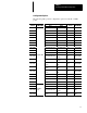
Power Supply Operating Voltage
AC units: 85-265 VAC 47-63 Hz
DC units: 21.6-26.4 VDC (24 VDC ± 10%)
Power Supply Fuse Protection
AC units: 120/240 VAC 1.25A
DC units: 24 VDC 1.6A
Power Supply Inrush Rating 30 Amperes maximum
Maximum Power Requirement
50 VA
➁
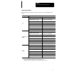
24 VDC User Power Output Current
➂
200mA
24 VDC User Power Output Voltage
➂
20.4 - 27.6 VDC (24 VDC ± 15 %)
Wire Size #14 AWG Max.
I/O Electrical-Optical Isolation 1500 VAC at 1 minute
1747-AIC Link Coupler
Electrical-Optical Isolation
1500 VDC
LED Indicators
POWER, PC RUN, CPU FAULT, FORCED I/O, and
BATTERY LOW
Noise Immunity NEMA Standard ICS 2-230
Ambient Temperature Rating
Operating: 0°C to +60°C (+32°F to +140°F)
Storage: 40°C to +85°C (-40°F to +185°F)
Humidity 5 to 95% without condensation
Displacement: .015 inch, peak-to-peak @ 5-57 Hz
Vibration
Acceleration: 2.5 Gs @ 57-2000 Hz
Duration: 1 hr per axis (x, y
, z)
Certification
UL listed/
CSA approved
➀
The scan times are typical for a 1K ladder logic program consisting of simple ladder logic and communication
servicing. Actual scan times depend on your program size, instructions used, and the DH-485
communication.
➁
This specification does not include input and output values. (See page
1-6.)
➂
This applies only to fixed controllers that have AC line power and DC input circuits.
Fixed Controller
Specifications