
Hardware Style Owner's manual


for Your Fixed Controller
Appendix E
Wiring and Circuit Diagrams and Voltage Ranges
E–35
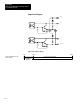
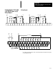
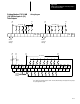
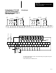
Wiring Diagram
VAC
1
OUT 0 OUT 1 OUT 2 OUT 3 OUT 4 OUT 5 NOT
USED
NOT
USED
V
AC 2
V
AC 2
V
AC 1
OUT 6 OUT 7 OUT 8 OUT 9 OUT 10 OUT 11 NOT
USED
NOT
USED
(Hi)
L1
CR CR
(Lo)
L2
V
AC 1
Connected
Internally
V
AC 2
Connected
Internally
CR CR CR CR
(Hi)
L1
(Lo)
L2
VAC
NEUT
NOT
USED
AC
COM
AC
COM
IN 1 IN 3 IN 5 IN 7 IN 9 IN 1
1
IN 13 IN 15 IN 17
NOT
USED
NOT
USED
NOT
USED
CHASSIS
GND
NOT
USED
AC
COM
AC
COM
IN 0 IN 2 IN 4 IN 6 IN 8 IN 10 IN 12 IN 14 IN 16
NOT
USED
NOT
USED
NOT
USED
120/240
VAC
85-132 V
AC
(Lo)
L2
(Hi)
L1
(Lo)
L2
(Hi)
L1
85 - 265
VAC
Commons
Connected
Internally
85-265 V
AC
85-265 V
AC
11
➀
These outputs are isolated in groups as shown. Therefore, different voltages can be applied to each group as
the specific application requires.
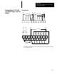
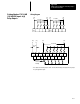
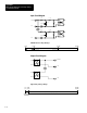
Catalog Number 1747-L30B
(18) 120 Vac Inputs & (12)
Triac Outputs