
Hardware Style Owner's manual


Control System
Appendix D
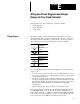
Calculating Heat Dissipation for the SLC 500
D–4
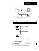
If your controller consisted of the following hardware components, you
would calculate heat dissipation as shown in the example worksheet below.
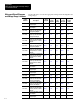
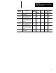
Hardware
Components
Catalog Number Minimum Watts Maximum Watts
Fixed Controller 1747-L20A 10.5 15.0
Input Module 1746-IA16 0.425 4.8
Output Module 1746-OA16 1.85 9.3
Peripheral Device 1747-DTAM 2.5 2.5
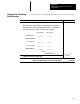
Example Worksheet for Calculating Heat Dissipation
Procedure Heat Dissipation
1. Calculate the heat dissipation for your fixed controller.
Write in the watts (calculated watts or maximum watts, see page D-1
)
dissipated by the controller, I/O and specialty modules, and peripheral
device attached to the controller. Add these values together.
Catalog Number Heat Dissipation
Fixed Controller _________ _________
Expansion Chassis
Slot 1 (if applicable) _________ _________
Slot 2 (if applicable) _________ _________
Peripheral Device _________ _________
Total: _________
Place Total on this Line --->
_______ W
2. Convert to BTUs/hr. Multiply the total heat dissipation of your SLC
500 fixed control system by 3.414.
x 3.414
Total heat dissipation of the SLC 500 control system:
_______
BTUs/hr
Example Heat Dissipation
Calculation