
Hardware Style Owner's manual


Appendix C
RS-232 Communication Interface
C–5
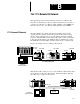
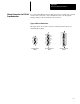
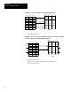
Pin Assignments for Wiring Connectors
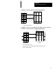
Use the following pin assignments to wire the connectors of Allen–Bradley
control devices with modems and peripheral devices that support RS–232
communication. See the table below to find the wiring diagram that you
need.
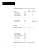
To Connect this
Device
To this Device Remarks
See this
Page
IBMAT
Modem Hardware Handshaking Enabled C-6
IBM AT
Peripheral DTE
Hardware Handshaking Disabled C-6
1747-KE
Modem Hardware Handshaking Enabled C-7
1747-KE
Peripheral DTE
Hardware Handshaking Disabled C-7
1746-BAS
Modem Hardware Handshaking Enabled C-8
1746-BAS
Peripheral DTE
Hardware Handshaking Disabled C-8
1770-KF3 Modem Hardware Handshaking Enabled C-8
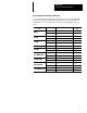
2760-RB
Modem Hardware Handshaking Enabled C-9
2760-RB
Peripheral DTE
Hardware Handshaking Disabled C-9
1771-KGM(PLC-2)
Modem Hardware Handshaking Enabled C-10
1771-KGM (PLC-2)
Peripheral DTE
Hardware Handshaking Disabled C-10
1775-KA(PLC-3)
Modem Hardware Handshaking Enabled C-11
1775-KA (PLC-3)
Peripheral DTE
Hardware Handshaking Disabled C-11
PLC-5(channel0)
Modem Hardware Handshaking Enabled C-12
PLC-5 (channel 0)
Peripheral DTE
Hardware Handshaking Disabled C-12
5130-RM(PLC-5/250)
Modem Hardware Handshaking Enabled C-13
5130-RM (PLC-5/250)
Peripheral DTE Hardware Handshaking Disabled C-13