
Hardware Style Owner's manual

Appendix A
Setting Up the DH-485 Network
A–12
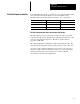
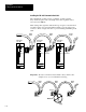
The table below shows wire/terminal connections for DH–485 connectors for
old Belden #9842.
For this Wire/Pair Connect this Wire To this Terminal
Shield/Drain Non-jacketed Terminal 2 - Shield
Black/White
Black
Cut back - no connection
➀
Black/White
White
Terminal 3 - (Common)
Black/Red
Black Terminal 4 - (Data B)
Black/Red
Red Terminal 5 - (Data A)
➀
To
prevent confusion when installing the communication cable, cut back the black wire immediately after the
the insulation jacket is removed. This wire is not used by DH-485.
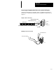
The table below shows wire/terminal connections for DH–485 connectors for
new Belden #9842.
For this Wire/Pair Connect this Wire To this Terminal
Shield/Drain Non-jacketed Terminal 2 - Shield
Blue/White
White with Blue Stripe
Cut back - no connection
➀
Blue/White
Blue with White Stripe
Terminal 3 - (Common)
White/Orange
White with Orange Stripe Terminal 4 - (Data B)
White/Orange
Orange with White Stripe Terminal 5 - (Data A)
➀
To
prevent confusion when installing the communication cable, cut back the white with blue stripe wire
immediately after the the insulation jacket is removed. This wire is not used by DH-485.
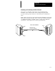
Important: In Series A 1747–AIC, terminal 5 was called DATA B and
terminal 4 was called DATA A. In this case, use terminal
numbers only and ignore signal names DATA B and DATA A.
The internal circuitry of the Series A is the same as Series B.