
USER MANUAL User Manual

Configuring the KFC15 Module 2-3
1747-5.34 - June 1998
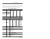
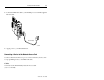
Documented in the tables below are the DIP switches, the bank in which
they are located, and the parameters controlled by each switch.
Table 2-1: Bank S1 DIP Switches
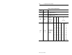
Table 2-2: Bank S2 DIP Switches
DIP Switch Parameter Description
Switches 1-3
Upper digit of
the DF1 station
address
SW 1/4
on
off
on
off
on
off
on
off
SW 2/5
on
on
off
off
on
on
off
off
SW 3/6
on
on
on
on
off
off
off
off
Digit
0
1
2
3
4
5
6
7 (default)
Switches 4-6
Lower digit of
DF1 station
address
Switches 7-8 Leave off
DIP Switch Parameters Description
Switches 1-3
Serial Port
Baud Rate
Switch 1
off
off
off
off
on
on
on
on
Switch 2
off
off
on
on
off
off
on
on
Switch 3
off
on
off
on
off
on
off
on
Baud Rate
1200 (default)
2400
4800
9600
19200
38400
57600
Reserved
Switch 4
Full/Half
duplex
off = Full duplex (default)
on = Half duplex
Switch 5 Parity
off = No parity (default)
on = See switch 6
Switch 6
Odd/Even
parity (when
used with
Switch 5)
off = Odd parity
on = Even parity
Switch 7 Handshake
off = No handshake (default)
on = Hardware handshake enable
Switch 8
Diagnostic
Command
Execution
off = Disabled (default)
on = Enabled