
Owner's manual

12 DH485/RS-232C Interface Module
Publication 1747-IN006B-EN-P - October 2005
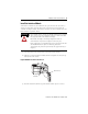
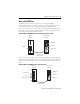
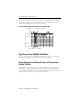
Wire the CONFIG and DF1 Communication Ports
The CONFIG and DF1 ports communicate to user devices through RS-232/423,
RS-422, and RS-485 communication modes. The communication mode you select
depends on the setting of jumpers JW1 and JW2.
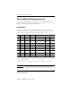
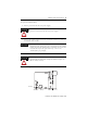
Pin Assignments
Use these pin assignments to wire the mating connector of the cable used to
interface a user device to CONFIG and DF1 ports. The sockets of this connector
must be wired to correspond to the selected communication mode.
The following illustrations show wiring diagrams for the RS-232/423, RS-422, and
RS-485 communications.
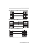
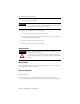
Pin RS-232/423 RS-422 RS-485 IBM AT Standard RS-232/423
Signal 25-pin 9-pin
1
(1)
TXD - TRXD - DCD or CD 8 1
2 RXD RXD -
(3)
(3) In RS-485 mode, these pins are still connected to their RS-422 receivers. Do not use these pins in RS-485 mode.
RXD 3 2
3TXD
(2)
(2) In RS-422 and RS-485 modes, these pins are connected to their RS-423 drivers and receivers. Do not use these pins in
either RS-422 or RS-485 mode.
(2)
TXD 2 3
4DTR
(2) (2)
DTR 20 4
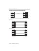
5 COMMON COMMON COMMON COMMON 7 5
6 DSR RXD +
(3)
DSR 6 6
7RTS
(2) (2)
RTS 4 7
8CTS
(2) (2)
CTS 5 8
9
(1)
(1) In RS-423 mode, these pins are still connected to their RS-422 loads. Do not use these pins in RS-423 mode.
TXD + TRXD + RI 22 9
IMPORTANT
The signal names on a DCE device are viewed from a DTE
perspective. For example, TXD is a DTE output and also a DCE
input.