Installation Instructions DH485/RS-232C Interface Module Catalog Number 1747-KE Inside . . .
DH485/RS-232C Interface Module Important User Information Solid state equipment has operational characteristics differing from those of electromechanical equipment. Safety Guidelines for the Application, Installation and Maintenance of Solid State Controls (Publication SGI-1.1 available from your local Rockwell Automation sales office or online at http://www.literature.rockwellautomation.com) describes some important differences between solid state equipment and hard-wired electromechanical devices.
DH485/RS-232C Interface Module 3 Hazardous Location Considerations This equipment is suitable for use in Class I, Division 2, Groups A, B, C, D or non-hazardous locations only. The following WARNING statement applies to use in hazardous locations. ATTENTION WARNING: EXPLOSION HAZARD Substitution of components may impair suitability for Class I, Division 2. Do not replace components or disconnect equipment unless power has been switched off.
DH485/RS-232C Interface Module About the DH485/RS-232C Module The DH485/RS-232C interface module, catalog number 1747-KE, is a communication interface module that acts as a bridge between DH485 networks and devices requiring DF1 protocol. The DF1 port on the interface module can be configured for RS-232/423, RS-422, or RS-485 devices. Residing in an SLC 500 chassis, the module is ideally used as an interface module, linking remote DH485 networks via a modem to a central host.
DH485/RS-232C Interface Module 5 The DF1 port is used to interface the module with user devices or a modem using DF1 protocol. This port is a serial port that accommodates RS-232/423, RS-422, and RS-485 communication modes. The DF1 port is capable of operating full-duplex at 300, 600, 1200, 2400, 4800, 9600, and 19200 Kbps. It is electrically isolated to 500V dc. The DH485 port is used to interface the module with the DH485 network.
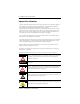
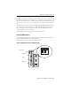
DH485/RS-232C Interface Module LED Color Status Indication ACT Green ON(1) The module is receiving power from the backplane, is configured correctly, and is in the Run mode. Flashing The module requires configuration or is being configured. OFF The module is not receiving power from the backplane. A fault condition exists. ON Port DH485 on the module is active for communication. OFF Port DH485 on the module is not active for communication or the module is in Configuration mode.
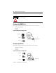
DH485/RS-232C Interface Module 7 functionality and mode of the interface module. The horizontal or vertical orientation of the jumper determines the module’s functionality. The position of the jumper determines the module’s mode (Configuration or Run), and thus, which method is used to configure the module (ASCII terminal or backplane communications). Figure 3 Jumper Locations JW1 CAT FRN SLC 500 INTERACE MODULE SER SERIAL NO.
DH485/RS-232C Interface Module Use a Modem with Your Interface Module The interface module can be connected to the following direct connect modems. • • • • Manual Data Terminal Equipment (DTE) Controlled Answer Auto Answer Direct Connect The manual modem is usually an acoustically-coupled modem. A person on each end of the phone line establishes the connection. The handset is inserted into an acoustic coupler to complete the connection.
DH485/RS-232C Interface Module 9 Set the Module’s Functionality Setting the module’s mode depends on which method you want to use to configure the module. You can configure the module using an ASCII terminal or backplane communication. IMPORTANT You can only use backplane communications if you selected series B functionality for the module. Configure the Module with an ASCII Terminal Configure the interface module with an ASCII terminal only when the JW4 jumper is in Configuration mode.
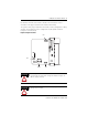
DH485/RS-232C Interface Module ATTENTION Other jumper settings are invalid and may cause damage to the interface module. Configure the CONFIG Port Jumper JW1 selects the following electrical interface for the CONFIG port. • RS-232/423 (default) • RS-422 • RS-485 Figure 7 JW1 Jumper Configurations RS-423/232 2 4 6 8 10 1 3 5 7 9 RS-422 JW1 CONFIG Port RS-485 Configure the DF1 Port Jumper JW2 selects the following electrical interface for the DF1 port.
DH485/RS-232C Interface Module 11 Install the Interface Module Your interface module may be installed in any open slot of an SLC 500 1746 I/O chassis except the first slot of the first chassis. The first slot is reserved for the controller or adapter module. The interface module can also be installed in an SLC fixed controller expansion chassis. ATTENTION Never install, remove, or wire any module while power is applied.
DH485/RS-232C Interface Module Wire the CONFIG and DF1 Communication Ports The CONFIG and DF1 ports communicate to user devices through RS-232/423, RS-422, and RS-485 communication modes. The communication mode you select depends on the setting of jumpers JW1 and JW2. Pin Assignments Use these pin assignments to wire the mating connector of the cable used to interface a user device to CONFIG and DF1 ports. The sockets of this connector must be wired to correspond to the selected communication mode.
DH485/RS-232C Interface Module 13 Figure 10 RS-232/423 DTE to DCE (Non-modem Hardware Handshake to DCE) NC 1 CD 1 8 RXD 2 3 4 RXD 2 3 4 3 2 20 5 6 7 6 7 8 9 4 5 22 TXD DTR TXD DTR 5 6 COM DSR COM DSR 7 8 9 RTS CTS NC RTS CTS RI Figure 11 RS-232/423 DTE to DCE (Modem Hardware Handshake to DCE) NC 1 CD 1 8 RXD 2 3 4 RXD 2 3 4 3 2 20 5 6 7 6 7 8 9 4 5 22 TXD DTR COM DSR RTS CTS NC TXD DTR 5 6 COM DSR 7 8 9 RTS CTS RI Figure 12 RS-232/423 DTE to DCE (No Handshake to D
DH485/RS-232C Interface Module Figure 13 RS-232/423 DTE to DCE (Soft or No Handshake to DCE) NC 1 CD 1 8 RXD 2 RXD 2 3 TXD 3 4 TXD DTR DTR 3 4 2 20 COM 5 COM 5 7 DSR 6 DSR 6 6 RTS 7 8 9 RTS 7 8 9 4 5 22 CTS NC CTS RI (1) (1) (1) Connect DSR to DTR and CD, and CTS to RTS when using devices that cannot disable their hardware handshaking.
DH485/RS-232C Interface Module 15 Wire to the DH485 Port The DH485 port can communicate to user devices through the DH485 Communication mode. Use a 1747-C10, 1747-C11, or 1747-C13 interface cable to connect the module to a link coupler interfaced with the DH485 network. If you use the 1747-C10 or 1747-C11 cable, it connects between the DH485 port on the interface module and the J1 (CPU) connector on the link coupler. Power for the link coupler comes from the interface module.
DH485/RS-232C Interface Module The 1747-C13 cable can also connect the interface module’s DH485 port directly to a single SLC controller or fixed controller. It connects the DH485 port on the module to the DH485 port on the SLC 500 controller.
DH485/RS-232C Interface Module 17 To replace the lithium battery: 1. Remove power from the SLC 500 power supply. ATTENTION Do not remove the module from the SLC 500 chassis until all power is removed from the SLC 500 power supply. 2. Remove the module from the chassis by pressing the retainer clips at the top and bottom of the module. IMPORTANT If the top or bottom retainer clips are broken while removing the module from the chassis, they can be easily replaced.
DH485/RS-232C Interface Module 3. Unplug the battery connector. IMPORTANT The module has a capacitor that provides 30 minutes of battery back-up while the battery is disconnected. Data in RAM is not lost if the battery is replaced within 30 minutes. 4. Remove the battery from the retaining clips. 5. Insert a new battery into the battery retaining clips. 6. Plug the battery connector into the socket with the red lead wire on top and the white lead wire on the bottom. 7.
DH485/RS-232C Interface Module 19 Three or More Batteries Procedures for the transportation of three or more batteries shipped together within the United States are specified by the Department of Transportation (DOT) in the Code of Federal Regulations, CFR49, “Transportation.” An exemption to these regulations, DOT - E7052, covers the transport of certain hazardous materials classified as flammable solids.
DH485/RS-232C Interface Module For a lithium battery material safety data sheet, contact the manufacturer. Sanyo Energy Corporation 600 Supreme Drive Tadarand Electronics or 2 Seaview Blvd.
DH485/RS-232C Interface Module 21 Specifications Specification Value Power Supply Loading at 5V dc 0.150 A (module only) 0.150 A (module with link coupler) Power Supply Loading at 24V dc 0.070 A (module only)(2)(3) 0.125 A (module with link coupler) Noise Immunity NEMA Standard ICS 2-230 Vibration Displacement: 0.015 in., peak-to-peak at 5...57 Hz Acceleration: 2.5 g at 57...
DH485/RS-232C Interface Module Certification Value Agency Certification c-UL-us listed Class I, Groups A, B, C or D, Division 2 CE compliant for all applicable directives C-Tick marked for all applicable acts Communication Max.
DH485/RS-232C Interface Module 23 Additional Resources For Refer to this document Pub. No. A more detailed description on how to install and use your modular SLC 500 controller. SLC 500 Modular Hardware Style User Manual 1747-UM011 A more detailed description on how to install and use your fixed SLC 500 controller. SLC 500 Fixed Hardware Style User Manual 1747-UM009 A more detailed description on how to install and use your RTD/resistance module.
Rockwell Automation Support Rockwell Automation provides technical information on the Web to assist you in using its products. At http://support.rockwellautomation.com, you can find technical manuals, a knowledge base of FAQs, technical and application notes, sample code and links to software service packs, and a MySupport feature that you can customize to make the best use of these tools.