
User Manual


Publication 1747-UM005B-EN-P - March 2006
Interpret the LED Indicators 7-3
Status Codes from the
Module to the Processor
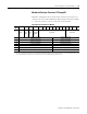
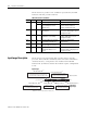
The module informs the SLC processor on the status of the configure
or read transaction by placing a status value in the Input Image file
word 0, bits 4 to 10. A value of 00 indicates that the status is okay.
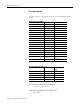
Status Codes from the Module to the SLC Processor
SLC Fault Code
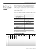
If a fault has occurred in the SLC system and the SLC fault code
indicates the slot the interface module is installed in, the fault might
be associated with the module I/O configuration. Refer to the table
below.
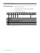
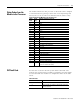
SLC Fault Codes
Value
(hex)
Value
(dec)
Indicates improper status for
01 01 Day
02 02 Month
03 03 Year
04 04 Day of the Week
05 05 Hour
06 06 Minute
07 07 Second
08 08 Data ID
09 09 (Not Used)
0A 10 (Not Used)
0B 11 DF1 Enq/Msg Retry
0C 12 Modem Init String Delay
0D 13 Master Station/NAK Rec Retry
0E 14 Slave Address/Group Number
0F 15 (Not Used)
10 16 DF1 Message Timeout
11 17 (Not Used)
12 18 RTS Off Delay
13 19 DH-485 Node Address
14 20 DH-485 Max Node Address
15 21 DH-485 Communication Rate
16 22 DH-485 Message TImeout
17 23 Modem Init String character
18 24 A write operation is attempted, but the configuration bit is not
set (still in software Run mode).
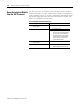
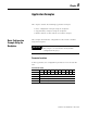
SLC Fault Code (S:6) Possible Reason
xx54
(1)
(1)
xx refers to the slot where the module is installed.
Wrong ID code was entered.
xx55
(1)
Wrong ID code was entered or wrong input and output
size were entered.