
User Manual


Publication 1747-UM005B-EN-P - March 2006
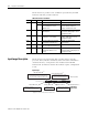
7-2 Interpret the LED Indicators
Shown below are possible error conditions represented by the LED
indicators and their possible solutions.
LED Indicator Error Conditions
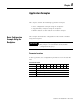
Input Image Description
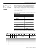
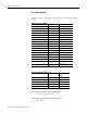
Shown below is the input image that provides status to the SLC
processor. Bit 13 indicates the battery status. The status information
contained in bit 13 corresponds to the module’s BA LOW LED
indicator. Bit 15 indicates whether the module requires configuration
or not.
Input Image
LED Color Status Condition Solution
ACT Green Flashing The module requires configuration. The module requires configuration.
OFF The module is not receiving power
from the backplane. A fault
condition exists.
Check the SLC power supply. Make
sure the interface module is
properly installed in the rack.
485 Green OFF The DH485 port is not active for
communication.
Check DH-485 cabling. Make sure
the module’s JW4 jumper is not in
Configuration mode.
DF1 Green OFF DF1 host is transmitting data and
LED indicator is not flashing.
Check DF1 cabling. Make sure the
module’s JW4 jumper is not in
Configuration mode.
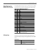
FAULT Red ON A system problem was detected
during background diagnostics.
Contact your Allen-Bradley
representative.
BA LOW Red ON The voltage of the battery that
backs up configuration RAM is low.
Replace battery.
CFG Green OFF The CONFIG port is transmitting
data and LED indicator is not
flashing.
Check ASCII terminal cabling. Make
sure the module’s JW4 jumper is in
Configuration mode.
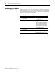
1 = Acknowledges that the module
was reset from the SLC processor.
0 = Module is running.
1 = Module requires configuring or is
in software Configuration mode.
Status Word, Word 0
B
i
t
N
u
m
b
e
r
(
d
ec
i
m
a
l
)
15 14 13 12 11 10 9 8 7 6 5 4 3 2 1 0
I:e.0
0 = Battery is good.
1 = Battery is low.
0 = Modem carrier detected.
1 = Modem carrier inactive
(no modem connected).
0 = Input image data may not be valid.
1 = SLC output image data is accepted by the
interface module. Input image data is valid.
Reset Acknowledge Bit
(1)
Data Handshake Bit
(1)
Status Code Bits
Data ID Value Bits
(1)
(echoed from
Output Image)
Modem Lost Bit
(1)
Battery Status Bit
Module Mode Bit
(1)
Applies to series B, or later, interface modules only.