
User Manual


Publication 1747-UM005B-EN-P - March 2006
6-14 Module Configuration Using the Backplane
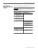
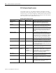
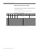
Modem Init String for Characters 1 Through 14
To set up string characters 1 to 14, build the configuration in the table
shown below. Please note that sending a ~ character produces a one
second wait on the modem.
Follow the configuration instructions found on page 6-2.
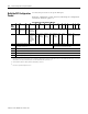
SLC Output File to the Interface Module
Bit
Word
15 14 13 12 11 10 9 8 7 6 5 4 3 2 1 0
0
(1)
Module
Mode
Bit
Data
Hand
shake
Bit
Read or
write
Bit
Reset
Interface
Module
Bit
Reserved Data ID=4
1 1st ASCII character 2nd ASCII character
2 3rd ASCII character 4th ASCII character
3 5th ASCII character 6th ASCII character
4 7th ASCII character 8th ASCII character
5 9th ASCII character 10th ASCII character
6 11th ASCII character 12th ASCII character
7 13th ASCII character 14th ASCII character
(1)
The output status word is defined on page 6-6. To configure the Modem Init String, the Read or Write Bit must be at 0 and the Module Mode Bit must be
at 1. To read the Modem Init String, the Read or Write Bit must be 1 and the Module Mode Bit can be either 0 or 1.