
User Manual

Publication 1747-UM005B-EN-P - March 2006
6-8 Module Configuration Using the Backplane
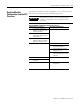
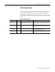
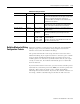
Build the DF1 Configuration
Packet
Use the SLC processor to set up the DF1 port.
Build the configuration packet shown by following the configuration
instructions found on page 6-2.
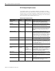
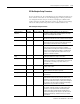
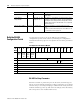
SLC Output File to the Interface Module
Bit
Word
15 14 13 12 11 10 9 8 7 6 5 4 3 2 1 0
0
(1)
Module
Mode
Bit
Data
Handshake
Bit
Read or
Write
Bit
Reset
Interface
Module Bit
Reserved Data ID=2
1 Embedded
Response
Detect
(Full) or
Local/Rem
ote Mode
(Half)
Half or
Full-
duplex
Constant
Carrier
Detect
(2)
Hardware
Hand-
shaking
(2)
Check
sum
Duplicate
Packet
Detection
Stop
Bits
Parity Bits per
Character
DF1
Communication
Rate
2 Modem Init String Delay (0...25 s) Enq/Msg Retries (0...254)
3 Slave Address (Local) (0...254)
Group Number (Remote) (0...7)
Master Station Address (Half Duplex) (0...254)
NAK Rec Retries (Full Duplex) (0...254)
4 ACK/POLL Timeout (0...65,535 x 5 ms)
5 Message Timeout (100...12,750 ms)
6
RTS ON Delay (0...65,535 x 5 ms)
(3)
7
RTS OFF Delay (0...65,499 x 5 ms)
(3)
(1)
The output status word is defined on page 6-6. To configure the DF1 parameters the Read or Write Bit must be 0 and the Module Mode Bit must be 1. To read the
DF1 parameters, the Read or Write Bit must be 1 and the Module Mode Bit can either be 0 or 1.
(2)
If Constant Carrier Detect is enabled, Hardware Handshaking is forced on.
(3)
The value is ignored if full-duplex is chosen.