
User Manual


Publication 1747-UM005B-EN-P - March 2006
Overview 1-3
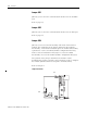
LED Indicators
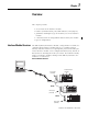
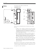
There are eight LED indicators on the front of the module. These LED
indicators are used for module diagnostics and operator interface. The
LED indicators and their descriptions are provided below.
LED Indicators
LED Indicator Status
DH
485
/
R
S
-
232
C
DH
485
/
R
S
-
232
C
AC
T
485
C
FG
D
F
1
F
AU
LT
BA
LO W
H
/
D
F/
D
I
N
TE
R
F
AC
E
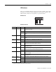
LED Color Status Indication
ACT Green
ON
(1)
The module is receiving power from the backplane, is configured properly, and
is placed in Run mode.
Flashing The module requires configuration or is being configured.
OFF The module is not receiving power from the backplane. A fault condition
exists.
485 Green ON The DH485 port is active on the network.
OFF The DH485 port is not active on the network or the module is in Configuration
mode.
CFG Green Flashing The CONFIG port is transmitting or receiving signals.
OFF The CONFIG port is not transmitting or receiving signals.
DF1 Green Flashing The DF1 port is transmitting or receiving signals. (The flashing may occur so
rapidly that the LED indicator appears to be on.)
OFF The DF1 port is not transmitting or receiving signals or the module is in
Configuration mode.
FAULT Red ON A system problem was detected during diagnostics. Cycle power to reset. If it
remains on, contact your Allen-Bradley representative.
OFF No system problems are detected during diagnostics.
BA LOW Red ON The voltage of the battery that backs up configuration RAM is low. A new
battery is needed.
OFF The voltage of the battery that backs up configuration RAM is at an
acceptable level.
H/D Amber ON The module is configured for half-duplex DF1 protocol (local or remote).
OFF The module is not configured for half-duplex DF1 protocol.
F/D Amber ON The module is configured for full-duplex DF1 protocol.
OFF The module is not configured for full-duplex DF1 protocol.
(1)
Indicates normal operation after the module has been configured.