
User Manual

Publication 1747-UM005B-EN-P - March 2006
Application Examples 8-15
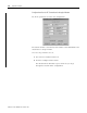
Configure the Module’s Serial Port
The steps below describe how to configure the interface module’s
serial port using an ASCII terminal.
However, you may use an alternate configuration method if you
choose (for example, ASCII terminal emulation software or backplane
communication). To configure the module’s serial port:
1. Place the interface module’s JW4 jumper into either horizontal or
vertical configuration mode, depending on which functionality
you chose.
See Chapter 4
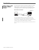
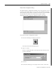
2. Connect an RS-232 cable between an ASCII terminal and the
interface module’s configuration port. Please refer to Chapter 4
for RS-232 cable pinouts between the interface module’s
configuration port and the ASCII terminal serial port.
Use one of the cable diagrams on page 4-8 for no hardware
handshaking.
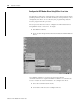
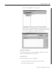
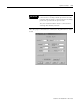
3. Configure the module. The DF1 port and the DH-485 settings for
the interface module are as shown below.
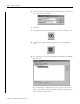
4. Once the interface module is configured, place the module’s
JW4 jumper into either horizontal or vertical Run mode,
depending on which functionality you chose.
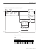
Setup Summary
Hit any key to continue. . . . .
Modem Init String = ATZ
CONFIG PORT DF1 PORT DH-485 PORT DF1 PRTCL (Full Dup)
Baud 1200 Baud 1200 Baud 19200 DPD Off. . . . . . . . . . . . . . . . . . . . . . . . . . . . .
Checksum CRC. . . . . . . .
Bits/char 8 Bits/char 8 Node 2 CCD Off. . . . . . . . . . . . . . . . . . . . . . . . . . . . . . . . .
Modem Init Delay 1S. . . .
Parity None Parity None Max Node Add 31 Msg Time 10000mS. . . . . . . . . . . . . . .
RTS/CTS Off. . . . . . . . . .
Stop Bits 1 Stop Bits 1 Msg Time 10000ms Em Resp Detect ADER. . . . . . . . . . . . .
ACK T ime 200x5mS. . . . .
Hndshking Soft Pass Thru Off ENQ Retries 2. . . . . . . . . . . . . . .
NAK Retries 2. . . . . . . . .