Important User Information Solid state equipment has operational characteristics differing from those of electromechanical equipment. “Application Considerations for Solid State Controls” (Publication SGI-1.1) describes some important differences between solid state equipment and hard–wired electromechanical devices.
Table of Contents Distributed I/O Scanner A–B Preface Using this Manual Purpose of this Manual . . . . . . . . . . . . . . . . . . . . . . . . . . . . . . . . . . . . . . Contents of this Manual . . . . . . . . . . . . . . . . . . . . . . . . . . . . . . . . . . . . . . Related Publications . . . . . . . . . . . . . . . . . . . . . . . . . . . . . . . . . . . . . . . . Intended Audience . . . . . . . . . . . . . . . . . . . . . . . . . . . . . . . . . . . . . . . . . . Conventions . . . . . . . . . . . .
Table of Contents Distributed I/O Scanner 30 I/O Block Configuration Input Image Example . . . . . . . . . . . . . . 30 I/O Block Configuration Output Image . . . . . . . . . . . . . . . . . . . . Control Word (Word 0) . . . . . . . . . . . . . . . . . . . . . . . . . . . . . . . . . . . 30 I/O Block Configuration Output Image Example . . . . . . . . . . . . Control Word Configuration Information . . . . . . . . . . . . . . . . . . . . . Use of the Communication Status Words . . . . . . . . . . . . . . . .
A–B P Preface Using This Manual Read this chapter to familiarize yourself with the rest of the manual. It provides information concerning the: • • • • contents of this manual intended audience conventions used warnings and cautions Purpose of this Manual This manual describes how the Distributed I/O (DIO) Scanner, Catalog Number 1747–DSN, is used in the Distributed I/O System.
Preface Related Publications The following publications are available to assist you in the use of your DIO system: • APS Library, Catalog Number 1747–ND001 Series B (shipped with Advanced Programming Software) • HHT Library, Catalog Number 1747–ND002 Series B (shipped with HHT) • SLC 500 Fixed and Modular Controller Library, Catalog Number 1747–ND003 Series A (shipped with SLC processor) • Block I/O User’s Manual, Publication 1701–6.5.
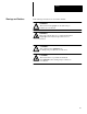
Preface Warnings and Cautions Both warnings and cautions are used in this manual. WARNING: ! This symbol means people can be injured if procedures are not followed. WARNING: This symbol means there is a potential shock hazard and people can be injured if procedures are not followed. ! CAUTION: This symbol means equipment can be damaged if procedures are not followed. CAUTION: This means there is a potential shock hazard and equipment can be damaged if procedures are not followed.
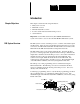
Chapter A–B 1 Introduction Chapter Objectives This chapter contains the following information: • DIO system overview • DIO Link overview • DH–485 Data Link overview • how the scanner interacts with the SLC processor • scanner features Important: Use the DIO scanner in any SLC 500 Modular Hardware system. The scanner cannot be used in SLC 500 Fixed Hardware systems. DIO System Overview The DIO system consists of an SLC processor, a scanner, an Isolated Coupler and I/O blocks.
Chapter 1 Introduction DIO Link Overview The DIO Link is an Allen–Bradley communications network supporting high speed transfer of control information. A DIO Link consists of a single master device (the scanner) and multiple slave devices (the I/O blocks). The scanner and I/O blocks are daisy chained together by a single twisted pair cable (Belden 9463). Each I/O block is assigned a I/O block number from 1 to 31 (excluding 16, which is invalid) by setting the appropriate dip switches on the I/O block.
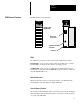
Chapter 1 Introduction DIO Scanner Features The DIO Scanner is featured below. SCANNER SN SCANNER FAULT LED COMM LED DIO Link Connector Chassis Ground Terminal Cable Tie LEDs Two LEDs are provided to monitor scanner and communications status. FAULT LED – used to monitor scanner status. Its normal state is off. The FAULT LED is off whenever the scanner is operating properly. COMM LED – used to monitor communications with the I/O blocks. Its normal state is solid green.
Chapter 1 Introduction How the Scanner Interacts with the SLC Processor The SLC processor scan consists of an input, program, and output scan. During the input scan, the scanner input file (which contains the on/off input status of all configured I/O blocks) is read into SLC processor memory. During the SLC program scan, the input information is used by your application program. An SLC output file, based on the logic of your program, is then written to the scanner during the output scan.
Chapter 1 Introduction Scanner Configurations The scanner can be configured for two different modes of operation. These modes, or configurations, are referred to as 7 and 30 I/O block configurations. When the scanner is configured for a 7 I/O block configuration, the scanner addresses up to seven I/O blocks. The SLC 5/01 and 5/02 processors support the 7 I/O block configuration. When the scanner is configured for a 30 I/O block configuration, the scanner addresses up to 30 I/O blocks.
Chapter A–B 2 Wiring and Installation Chapter Objectives This chapter contains the information necessary to: • • • • Determining Block Requirements select the proper DIO system components install the scanner into the SLC Rack wire the DIO Link Network wire the DH–485 Data Link Network The number of I/O blocks you require is based upon the number of input and output devices called for in your functional specification. The proximity of each device must also be taken into consideration.
Chapter 2 Wiring and Installation Wiring the DIO Link The scanner and I/O blocks are connected to the DIO Link in a daisy chain configuration. A daisy chain configuration is formed by connecting the scanner and I/O blocks together in a serial manner along a single section of link cable (Belden 9463). The scanner is attached to the DIO Link using its 3 position DIO Link connector, and the I/O blocks are attached to the DIO Link using 3 terminals on their 6 position DIO connector.
Chapter 2 Wiring and Installation The DIO Link must be terminated at each end with an 82 Ohm 1/2 watt resistor. The resistor is connected across Line 1 and Line 2. In addition, Chassis Grounding Method One is illustrated below.
Chapter 2 Wiring and Installation Wiring the DH–485 Data Link The DH–485 Data Link allows a programming device to communicate with the SLC processor. Each I/O block has a programming port that allows a programming device to be connected to the DH–485 Data Link. The Isolated Coupler and I/O blocks are connected to the DH–485 Data Link in a daisy chain configuration.
Chapter 2 Wiring and Installation The Isolated Coupler is attached to the DH–485 Data Link using its 6 position DH–485 Data Link connector. The I/O blocks are attached to the DIO Link using 4 of the 6 terminals on the DIO connector. The DH–485 Data Link cable shield must be earth grounded at one point on the link. The SLC processor is connected to the Isolated Coupler with a Catalog Number 1747–C11 Communication Cable, which is included with the Isolated Coupler.
Chapter 2 Wiring and Installation Scanner Installation Installation procedures for this scanner are the same as any other discrete I/O or specialty module. ! CAUTION: Disconnect power before attempting to install, remove, or wire the scanner. 1. Align the full sized scanner circuit board with the rack card guide. The first slot (slot 0) of the first rack is reserved for the SLC processor. 2. Slide the scanner into the rack until the top and bottom latches are latched.
Chapter A–B 3 Configuration and Programming Chapter Objectives This chapter contains the information necessary to: • configure the SLC processor for use with the scanner • access the I/O block data in the SLC processor input and output files • configure the scanner for the correct number of I/O blocks • disable the I/O block outputs • monitor the communication status of the DIO Link
Chapter 3 Configuration and Programming SLC Processor Configuration The scanner can be configured to communicate with a maximum of 7 or 30 I/O blocks. The 7 or 30 I/O block configuration is determined by the ID code that is entered when programming the SLC processor. SLC 5/01 processors can only use the 7 I/O block configuration. SLC 5/02 processors can use either the 7 or 30 I/O block configuration.
Chapter 3 Configuration and Programming SLC Processor Input and Output Images The SLC processor input and output images for the scanner are dependent upon whether the 7 I/O block or 30 I/O block configuration is selected. 7 I/O Block Configuration Input Image The 7 I/O block configuration input image consists of eight words (one communication status word and seven input words). Each input word corresponds to an I/O block address. For example, the input data for I/O block 7 is located in input word 7.
Chapter 3 Configuration and Programming 7 I/O Block Configuration Output Image The 7 I/O block Configuration Output Image consists of eight words (one control word and seven output words). Each output word corresponds to an I/O block address. For example, the output data for I/O block 7 is located in output word 7. In addition, the bits of each output word correspond to the outputs on the I/O block. For example, • For I/O blocks with 6 outputs, bits 0 – 5 are valid.
Chapter 3 Configuration and Programming Configuration Data Valid Bit – Bit 10 of the Control Word (word 0) must be set after bits 0 – 4 (Number of I/O blocks) are valid. When this bit is first set to 1 (from within the run mode), bits 0 – 4 (Number of I/O blocks) are used to configure the scanner with the number of I/O blocks connected. Important: This bit should not be reset to 0 during program execution. Once this bit is set, further transitions of bits 0 – 4 (Number of I/O blocks) are ignored.
Chapter 3 Configuration and Programming 30 I/O Block Configuration Input Image The 30 I/O block configuration input image consists of 32 words (two communication status words and 30 input words). Each input word has a corresponding I/O block address. For example, the input data for I/O block 31 (there is no I/O block 16) is located in input word 31. In addition, the bits of each input word correspond to the inputs on the I/O block. For example, • For I/O blocks with 8 inputs, bits 0–7 are valid.
Chapter 3 Configuration and Programming 30 I/O Block Configuration Input Image Example Bits 1 – 15, I/O block communication status for I/O blocks 1 – 15 Bit Number (decimal) 15 14 13 12 11 10 Bit 0, Overall communication status for I/O blocks 1–15 and 17–31 9 8 7 6 5 4 3 2 1 0 Input File I:e.0 I/O block Communication Status, Word 0 I/O block 1 Input, Word 1 I:e.1 Reserved Communication status for I/O blocks 17–31, Word 16 I:e.
Chapter 3 Configuration and Programming 30 I/O Block Configuration Output Image The 30 I/O block configuration output image consists of 32 words (one control word, one reserved word, and 30 output words). Each output word has a corresponding I/O block address. For example, the output data for I/O block 31 (there is no I/O block 16) is located in output word 31. In addition, the bits of each output word correspond to the outputs on the I/O block.
Chapter 3 Configuration and Programming Configuration Data Valid Bit – Bit 10 of the Control Word (word 0) must be set after bits 0 –4 (Number of I/O blocks) are valid. When this bit is first set to 1 (from run mode), bits 0 – 4 are used to configure the scanner with the number of I/O blocks connected to the scanner. Important: This bit should not be reset to 0 during program execution. After this bit is set, further transitions of bits 0 – 4 (Number of I/O blocks) are ignored.
Chapter 3 Configuration and Programming Use of the Communication Status Words The bits in the Communication Status Word(s) indicate whether or not the scanner is communicating with each of the configured I/O blocks. Each bit in the Communication Status Word(s) corresponds to an I/O block. If the scanner is communicating with an I/O block, the corresponding bit in the Communication Status Word is set to 1.
Chapter 3 Configuration and Programming The Output Disable bit can be used anytime that the SLC processor is in run mode. The bit has no effect when the processor is in program/test/fault mode. The Output Disable bit is not affected by, and does not affect, the bits for Data Valid or Number of I/O Blocks.
Chapter 3 Configuration and Programming Programming Example Using 7 I/O block Configuration In the following programming example, the first rung is used to initiate the DIO system using the Output Control Word. The scanner is located in slot 1 and an alarm is connected to a discrete I/O card in slot 2. When the water level drops, the switch closes and the pump starts pumping water into the tower.
Chapter A–B 4 Operation and Troubleshooting Chapter Objectives This chapter will provide information on : • scanner start–up • scanner normal operation • scanner test mode operation • scanner slot disable operation • I/O block hold last state operation • scanner and I/O block status LEDs • troubleshooting the scanner and DIO Link • SLC processor error codes for the scanner Start Up The following steps will assist you in the start up of your DIO Link.
Chapter 4 Operation and Troubleshooting Normal Operation During normal operation, the LEDs are illuminated as shown below: SCANNER COMM DSN FAULT FAULT LED is off COMM LED is solid green When the SLC processor is taken out of run mode, the COMM LED remains solid green. The inputs of the blocks connected to the scanner are still read. However, I/O block outputs are set to 0 (disabled).
Chapter 4 Operation and Troubleshooting Scanner Slot Disable Operation ! CAUTION: Make sure that you clearly understand the implications of disabling a scanner module slot before utilizing this feature. The scanner slot disable operation is the same in the 7 I/O and 30 I/O block configurations.
Chapter 4 Operation and Troubleshooting Scanner Test Mode Operation The scanner test mode operation is different for the 7 I/O block and 30 I/O block configurations. 30 I/O block Configuration For the 30 I/O block configuration, the Number of I/O Blocks and Configuration Data Valid bits will operate in test mode in the same manner as they operate in run mode.
Chapter 4 Operation and Troubleshooting I/O Block Hold Last State Operation During normal operation, the I/O block outputs reflect the SLC processor output image. However, there are several conditions under which the I/O block outputs will not reflect the SLC processor output image, but will either be reset to 0 or will hold their last state.
Chapter 4 Operation and Troubleshooting Status LEDs The scanner has two LEDs that indicate its operating status, FAULT and COMM. The FAULT LED indicates the scanner’s overall status. The COMM LED indicates the DIO Link communications status. The FAULT LED is off whenever the scanner is operating properly. The COMM LED state is valid only when the FAULT LED is off. The table below provides the scanner and communications status as indicated by the FAULT and COMM LEDs.
Chapter 4 Operation and Troubleshooting Troubleshooting COMM SCANNER When the scanner’s LEDs change state, use the following table to isolate the cause. FAULT LED Condition Problem Solution FAULT LED flashing red Configured for an invalid number of I/O blocks. Modify DIO initialization rung in SLC program to reflect the correct number of I/O blocks. FAULT LED solid red Duplicate scanner detected, or hardware error on scanner. Disconnect DIO Link from scanner and cycle scanner power.
Chapter 4 Operation and Troubleshooting Error Codes Error codes are reported in word 6 of the SLC processor status file. The format of the status word and applicable error codes are shown below: Slot Number 01H to 1EH Error Code . The table below lists and explains the possible errors that you may encounter using an SLC 5/01 or 5/02 processor with the DIO scanner.
Chapter A–B 5 Specifications Chapter Objectives Scanner Operating Specifications This chapter provides the scanner specifications. Backplane Current Consumption 900 mA @ 5VDC Operating Temperature +32°F to 131°F (0°C to +55°C) Storage Temperature –40°F to 185°F (–40°C to +85°C) Humidity 5 to 95% without condensation Noise Immunity NEMA Standard ICS 2–230 Processor Type SLC 5/01 or above * * Scanners cannot be used with SLC 500 Fixed System. Network Specifications 230.