
Instruction Manual

Direct Communication Module 15
Publication 1747-IN005B-EN-P - March 2003
Troubleshooting
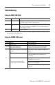
Using the FAULT LED (Red)
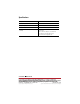
Using the COMM LED (Green)
If LED is: Cause: Corrective Action:
On Internal Fault Cycle power to the I/O chassis containing the 1747-DCM. Replace the
1747-DCM if red LED remains lit after power-up.
Flashing Configuration
Error
Check that the DIP switch settings are correct. Make sure that I/O group
and chassis size settings are compatible.
(1)
Also see that the setting for
chassis address is correct.
(1) The 1747-DCM cannot cross logical chassis boundaries. For example, configuring the module for ½ logical chassis with
starting group 6 causes a configuration error.
Off Normal State No action required.
If LED is: Cause: Corrective Action:
On Normal State No action required.
Flashing RIO scanner’s processor in
Program/Test/Fault mode
Check for RIO scanner’s processor error, correct
condition, and cycle power to the 1747-DCM.
Off
RIO scanner’s processor not connected to
scanner
Check that the scanner is properly installed in the
chassis.
RIO scanner’s processor chassis inhibited Check RIO scanner’s processor chassis integrity,
correct any problem, and cycle power to the
1747-DCM.
No communication between RIO
scanner’s processor and 1747-DCM
Check that the baud rate of the 1747-DCM matches
the baud rate of the scanner.
Check cable connections from the RIO scanner or its
processor to the 1747-DCM.
Check that the 1747-DCM connector is properly
installed.