
Instruction Manual

14 Direct Communication Module
Publication 1747-IN005B-EN-P - March 2003
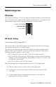
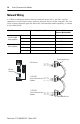
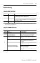
Network Wiring
A ½ Watt terminating resistor must be attached across line 1 and line 2 of the
connectors at each end (scanner and last physical device) of the network. The size
of the resistor depends upon the baud rate and extended node capability, as shown
in the table below.
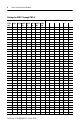
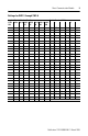
Baud Rate Terminating Resistor Size Maximum Cable
Distance (Belden 9463)
Using Extended
Node Capability
57.6K baud 82Ω ½ Watt Grey-Red-Black-Gold 3048 m (10,000 ft.)
115.2K baud 82Ω ½ Watt Grey-Red-Black-Gold 1524 m (5,000 ft.)
230.4K baud 82Ω ½ Watt Grey-Red-Black-Gold 762 m (2,500 ft.)
Without Extended
Node Capability
57.6K baud 150Ω ½ Watt 3048 m (10,000 ft.)
115.2K baud 150Ω ½ Watt Brown-Green-Brown-Gold 1524 m (5,000 ft.)
230.4K baud 82Ω ½ Watt Grey-Red-Black-Gold 762 m (2,500 ft.)
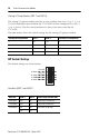
Line 1 - Blue
Shield - Shield
Line 2 - Clear
Line 1 - Blue
Shield - Shield
Line 2 - Clear
Line 1 - Blue
Shield - Shield
Line 2 - Clear
DCM
COMM
FAULT
CONFIGURATION
RACK SIZE
1/4 1/2 3/4 1
RACK ADDR
FIRST I/O GROUP
0 2 4 6
DATA RATE (K B/S)
57.6 115.2 230.4
LINE 1 _______
SHIELD ______
LINE 2 _______
1747±DCM
SW2
SW1
O
N
12345678
O
N
12345678
I/O
GROUP
(LSB)
RACK
ADDRESS
(MSB)
RACK
SIZE
DATA
RATE
X
X
LAST RACK
CLR ON FLT
Terminating Resistor
Terminating Resistor
1747-DCM
Direct Communication
Module
1747-DCM
Direct Communication
Module
RIO Scanner
RIO Link
Connector