
Instruction Manual

12 Direct Communication Module
Publication 1747-IN005B-EN-P - March 2003
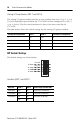
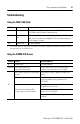
Chassis Size (SW2-5 and SW2-6)
The logical chassis size allocates image space in the scanner for each 1747-DCMs
I/O data. The 1747-DCM allows ¼, ½, ¾, and full chassis addressing. SW2 switches
5 and 6 define the chassis size, as shown below.
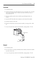
Installation and Removal
Power Requirements
Before installation, make sure your modular SLC power supply has adequate
reserve current capacity. The 1747-DCM requires 360 mA at 5V dc.
Each fixed SLC 500 controller can support one 1747-DCM in a 2-slot expansion
chassis, depending on which I/O module is in the second slot. See Discrete Input
and Output Modules Technical Data, publication number 1746-2.35 for details.
Chassis Size SW2-5 SW2-6 Number of RIO Words Transferred Total Words
¼ Logical Chassis ON ON 1 Status and 1 Data 2
½ Logical Chassis ON OFF 1 Status and 3 Data 4
¾ Logical Chassis OFF ON 1 Status and 5 Data 6
Full Logical Chassis OFF OFF 1 Status and 7 Data 8
IMPORTANT
The 1747-DCM image cannot cross logical chassis boundaries. For
example, configuring the module for ½ logical chassis with
starting group 6 will cause a configuration error.
ATTENTION
!
Disconnect power before attempting to install, remove, or wire
the 1747-DCM.
IMPORTANT
Make sure you have set the DIP switches properly before
installing the 1747-DCM. See Module Configuration on page 7.