
User Manual


Publication 1747-UM010B-EN-P - September 2003
5-32 Configuration and Programming
Understanding Slot
Addressing
This section provides information about:
• 2-slot addressing
• 1-slot addressing
• 1/2-slot addressing
Understanding slot addressing is critical to most efficiently allocate
your scanner’s I/O image files.
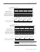
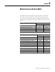
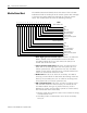
Slot addressing refers to how each remote chassis slot is assigned a
specific amount of the I/O image. The amount depends on which
type of slot addressing you choose at your adapter; 2-slot, 1-slot, and
1/2-slot addressing is available, as shown below:
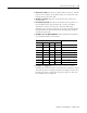
For more information on slot addressing, refer to your ASB module
user manual.
Note that slot addressing (e.g., 1/2-, 1-, and 2-slot) may not apply to
all types of RIO devices. Refer to each RIO device’s user manual to
determine the type of slot addressing required.
07815 07815
07815 07815
07815 07815
Two slots are addressed as one logical group.
Input Image Output Image
2-Slot
Addressing
Remote Chassis
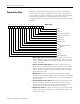
1-Slot
Addressing
Remote Chassis
One slot is addressed as one logical group.
Input Image Output Image
1/2-Slot
Addressing
Remote Chassis
One slot is addressed as two logical groups.
Input Image Output Image
Slot 2 Slot 2Slot 1 Slot 1
Slot 1 Slot 1
Slot 1 Slot 1