
User Manual

Publication 1747-UM010B-EN-P - September 2003
Installation and Wiring 3-5
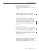
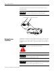
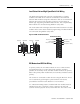
Insertion
1. Disconnect power.
2. Align the full-sized circuit board with the chassis card guides.
The first slot (slot 0) of the first rack is reserved for the SLC 500
processor.
3. Slide the module into the chassis until the top and bottom
latches catch.
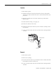
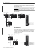
4. Install terminal wiring. See page 3-6.
5. Insert the cable tie in the slots.
6. Route the cable down and away from module, securing it with
the cable tie.
7. Cover all unused slots with the Card Slot Filler, Catalog Number
1746-N2.
Removal
1. Disconnect power.
2. Remove all cabling.
3. Press the releases at the top and bottom of the module and slide
the module out of the chassis slot.
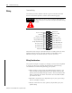
4. Cover all unused slots with the Card Slot Filler, Catalog Number
1746-N2.
Module Release
Card Guide
Cable Tie