
User Manual


Publication 1747-UM010B-EN-P - September 2003
1-12 Overview
Guidelines for Configuring Complementary I/O
When you configure your remote system for complementary I/O,
follow these guidelines:
• You can place an output module in the primary chassis opposite
another output module in the complementary chassis; they use
the same bits in the output image table. However, we do not
recommend this placement of modules for redundant I/O.
• You cannot use complementary I/O with a chassis that uses
32-point I/O modules and 1-slot addressing or 16-point I/O
modules with 2-slot addressing.
• Do not place an input module in the primary chassis opposite
an input module in the complementary chassis because they use
the same bits in the input image table.
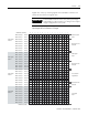
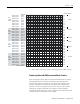
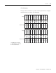
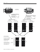
2-Slot Addressing
The figures below illustrate a possible module placement to configure
complementary I/O using 2-slot addressing.
I
8
O
8
I
16
I
8
I
8
O
8
O
16
O
8
OBT BT
8
O
8
O
8
O
8
I
8
I
8
I
8
I
8
O
8
1
012345
I
16
I
16
I
16
O
16
O
16
O
16
012345
I
16
I
16
I
16
O
16
O
16
O
16
1
E
M
P
T
Y
Outputs in the complementary chassis would use the same bits in the
output image table as the outputs in the primary chassis. You cannot
place inputs in the complementary chassis.
E
M
P
T
Y
E
M
P
T
Y
E
M
P
T
Y
E
M
P
T
Y
Primary
I = Input Module (8- or 16-point)
O = Output Module (8- or 16-point)
BT = Block Transfer Module
Primary
Complementary
Complementary
(1) Must be empty if corresponding primary slot is a block transfer module.
IMPORTANT
With 2-slot addressing, if an input module resides in
either slot associated with a logical group of the
primary chassis, an input module cannot reside in
that logical group's complementary chassis.