
User Manual


Publication 1747-UM010B-EN-P - September 2003
1-8 Overview
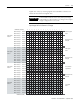
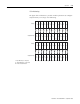
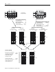
Example Scanner I/O Image
The illustration below shows a scanner’s input image of 4 RIO link
devices.
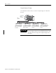
SLC 5/02 or
Later
Processor
RIO
Scanner
Full Logical Rack Device
Begins at Logical Rack
0, Group 0
Three-Quarter Logical Rack
Device Begins at Logical
Rack 1, Group 0
Half Logical Rack Device
Begins at Logical Rack 2,
Group 0
Quarter Logical Rack Device
Begins at Logical Rack 2,
Group 4
Device 1 Device 2
Device 3
Device 4
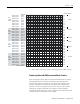
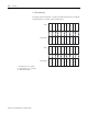
IMPORTANT
The illustration on the following page shows how
the 1747-BSN scanner’s input image translates to the
SLC 500 processor image. The output image looks
the same.