Backup Scanner Module (Catalog Number 1747-BSN) User Manual
Important User Information Because of the variety of uses for the products described in this publication, those responsible for the application and use of these products must satisfy themselves that all necessary steps have been taken to assure that each application and use meets all performance and safety requirements, including any applicable laws, regulations, codes and standards.
Summary of Changes The information below summarizes the changes to this manual since the last printing. To help you find new and updated information in this release of the manual, we have included change bars as shown to the right of this paragraph. The table below lists the pages or sections containing new or revised information.
Summary of Changes Publication 1747-UM010B-EN-P - September 2003
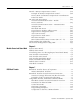
Table of Contents Preface Who Should Use This Manual . . . . . . . . . . . . . . How to Use This Manual . . . . . . . . . . . . . . . . . . Manual Contents . . . . . . . . . . . . . . . . . . . . . Related Documentation . . . . . . . . . . . . . . . . Conventions Used in This Manual . . . . . . . . . . . Rockwell Automation Support . . . . . . . . . . . . . . Your Questions or Comments on the Manual . . . . . . . . . . . . . . . . . . . . . . . . . . . . . . . . . . . . . . . . . . . . . . . . . . .
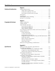
Table of Contents ii Configuration Selection . . . . . . . . . . . . . . . . . . . . . . . . . Backup Scanner Installation. . . . . . . . . . . . . . . . . . . . . . Insertion . . . . . . . . . . . . . . . . . . . . . . . . . . . . . . . . . Removal . . . . . . . . . . . . . . . . . . . . . . . . . . . . . . . . . Wiring . . . . . . . . . . . . . . . . . . . . . . . . . . . . . . . . . . . . . Wiring Considerations . . . . . . . . . . . . . . . . . . . . . . .
Table of Contents iii M0 File - Remote Output Reset Control . . . . . . . . . . . . . . . Example of Remote Output Reset Control . . . . . . . . . . . Device Reset and Remote Output Reset Considerations From This Mode . . . . . . . . . . . . . . . . . . . . . . . . . . . . . M1 Status File Description . . . . . . . . . . . . . . . . . . . . . . . . . General Communication Status - Enable Device Fault Bit . . . . . . . . . . . . . . . . . . . . . . . . . . . . . .
Table of Contents iv Chapter 8 Switchover Considerations Timing Requirements . . . . . . . . . . . . . Input Signal Update Time. . . . . . . . Time-out on Remote I/O Link . . . . Data Table Transfer Time on HSSL . Divergence . . . . . . . . . . . . . . . . . . . . . Forcing I/O. . . . . . . . . . . . . . . . . . . . . Data Highway Plus Switching . . . . . . . Remote I/O Switching . . . . . . . . . . . . . . . . . . . . . . . . . . . . . . . . . . . . . . . . . . . . . . . . . . . . . . . . . . . .
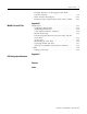
Table of Contents v Example Discrete I/O Throughput with Block Transfers Present . . . . . . . . . . . . . . . . . . . . . . . . . . . . . A-9 Block Transfer Throughput . . . . . . . . . . . . . . . . . . . . A-11 Backup Scanner Output Delay Time (TSNo) Tables. . . A-14 Appendix B M0-M1 Files and G Files M0-M1 Files . . . . . . . . . . . . . . . . . . . . . . . . . . . . . . . Configuring M0-M1 Files . . . . . . . . . . . . . . . . . . . Addressing M0-M1 Files . . . . . . . . . . . . . . . . . . . .
Table of Contents vi Publication 1747-UM010B-EN-P - September 2003
Preface Read this preface to familiarize yourself with the rest of the manual. This preface covers the following topics: • • • • • who should use this manual how to use this manual related publications conventions used in this manual Allen-Bradley support Who Should Use This Manual Use this manual if you are responsible for designing, installing, programming, or troubleshooting control systems that use Allen-Bradley small logic controllers.
2 Preface Related Documentation The table below provides a listing of publications that contain important information about Allen-Bradley SLC products.
Preface Rockwell Automation Support 3 Rockwell Automation tests all of our products to ensure that they are fully operational when shipped from the manufacturing facility. If you are experiencing installation or startup problems, please review the troubleshooting information contained in this publication first. If you need technical assistance to get your module up and running, please contact Customer Support (see the table below); our trained technical specialists are available to help.
4 Preface Publication 1747-UM010B-EN-P - September 2003
Chapter 1 Overview This chapter contains the following information: • • • • • • • • • System Overview system overview how the backup scanner interacts with the SLC processor how the backup scanner interacts with adapter modules scanner I/O image concepts extended node capability complementary I/O scanner features compatible network devices backup concepts for the SLC-500 system The 1747-BSN Backup Scanner provides redundancy for: • Remote I/O (RIO) • RS232 channel switchover for communications to devi
1-2 Overview remotely located (3,048 meters [10,000 feet] maximum) 1746 I/O chassis and other RIO-compatible Allen-Bradley operator interface and control devices. The 1747-SN scanner communicates with remotely located devices using the A-B Remote I/O link. The RIO link consists of a single master (scanner) and multiple slaves (adapters). Communication between devices occurs over twinax cable with the devices daisy-chained together.
Overview 1-3 SLC 5/02 or Later Processor RIO Scanner The scanner transfers discrete input and output data between itself, remote adapters, and the SLC processor. Remote adapters consist of 1746 chassis and other Allen-Bradley operator interface and control devices.
1-4 Overview Backup Scanner I/O Image Division The backup scanner allows each adapter to use a fixed amount (user-defined) of the scanner’s input and output image. Part of the SLC processor’s image is used by local I/O; the other portion is used by the scanner for remote I/O. The scanner’s remote I/O image is divided into logical racks and further divided into logical groups. A full logical rack consists of eight input and eight output image words.
Overview 1-5 Backup Scanner Scan The scanner updates its input image file each time it scans a logical device. Scanner Input Image File Output Device 3 Input Device 1 Output Device 1 Input Device 3 Output Device 2 Input Device 2 Scanner Output Image File SLC and Scanner Asynchronous Operation The SLC processor scan and Backup scanner scan are independent (asynchronous) of each other.
1-6 Overview How the Scanner Interacts with Adapters The scanner’s function is to continuously scan the adapters on the RIO link in a consecutive manner. This scan consists of one or more RIO discrete transfers to each adapter on the RIO link. RIO discrete transfers consist of the scanner sending output image data and communication commands to the adapter that instruct the adapter on how to control its output. (These include run, adapter reset, and reset decide commands.
Overview 1-7 logical rack. Also, by crossing logical rack boundaries a device can consist of more than one logical rack. The illustration below shows only the input image configuration of the scanner’s I/O image. The output image configuration is the same.
1-8 Overview Example Scanner I/O Image The illustration below shows a scanner’s input image of 4 RIO link devices.
Overview RIO Logical Rack 0 RIO Logical Rack 1 RIO Logical Rack 2 RIO Logical Rack 3 Bit Number Word 0 Rack 0 Group 0 Word 1 Rack 0 Group 1 Word 2 Rack 0 Group 2 Word 3 Rack 0 Group 3 Word 4 Rack 0 Group 4 Word 5 Rack 0 Group 5 Word 6 Rack 0 Group 6 Word 7 Rack 0 Group 7 Word 8 Rack 1 Group 0 Word 9 Rack 1 Group 1 Word 10 Rack 1 Group 2 Word 11 Rack 1 Group 3 Word 12 Rack 1 Group 4 Word 13 Rack 1 Group 5 Word 14 Rack 1 Group 6 Word 15 Rack 1 Group 7 Word 16 Rack 2 Group 0 Word 17 Rack 2 Group 1 Word 18
1-10 Overview Through your control program you command the SLC processor to initiate RIO block transfers, which directs the scanner to exchange large amounts of data to/from an adapter. Block Transfers (BTs) use the basic RIO discrete transfer mechanism of the RIO link. However, the actual transfer of data occurs asynchronous to the discrete transfers. It is possible for several discrete transfers to occur before the scanner processes a block transfer.
Overview 1-11 same slot of the complementary chassis. This enables total use of the scanner’s 32 input and 32 output word image for I/O addressing of up to 1024 discrete points. ATTENTION ! Because the primary and complementary chassis images overlap, input and specialty combination I/O modules must never share the same image location. Inputs received by the scanner may be incorrect and RIO block transfers will not be serviced properly.
1-12 Overview Guidelines for Configuring Complementary I/O When you configure your remote system for complementary I/O, follow these guidelines: • You can place an output module in the primary chassis opposite another output module in the complementary chassis; they use the same bits in the output image table. However, we do not recommend this placement of modules for redundant I/O.
Overview 1-13 1-Slot Addressing The figure below illustrates a possible module placement to configure complementary I/O using 1-slot addressing.
1-14 Overview 1/2-Slot Addressing The figure below illustrates a possible module placement to configure complementary I/O using 1/2-slot addressing.
Overview 1-15 Summary for Placing Modules Used In Complementary I/O Discrete Modules Addressing Types of Modules Method used Placement 2-slot 8-point Install input modules opposite output modules, and output modules opposite input modules.(1) 1-slot 8-point, 16-point Install input modules opposite output modules, and output modules opposite input modules. 1/2-slot 8-point, 16-point, 32-point Install input modules opposite output modules, and output modules opposite input modules.
1-16 Overview O I I O I O I O I O O I O I O I 3 7 I = Input Module O= Output Module 0 Slot Pair 1 2 1 3 4 2 5 6 7 3 8 0 4 Primary Chassis 10 7 8 7 Slot 1 Slot 1 Slot 1 Slot 1 Slot 1 Slot 1 Slot 1 Slot 1 Slot 1 Slot 1 Slot 1 Slot 1 Slot 1 Slot 1 Slot 1 Slot 1 1 0 Octal 0 Decimal Slot 1 Slot 1 1 Slot 1 Slot 1 Slot 1 Slot 1 2 Slot 1 Slot 1 Slot Pair Slot 1 Slot 1 3 Slot 1 Slot 1 Slot 1 Slot 1 4 Slot 1 Slot 1 17 15 Slot 1 Slot 1 Slot 1 Slot 1 Slot 1 Slot 1 Slot 1 Slot 1 Slot 1
Overview 1-17 Application Considerations If you configure a complementary device to use more I/O image space than an associated primary device, then block transfers can only be performed to locations in the complementary device that have associated I/O image space in the primary device. For example, if a primary device is 1/2 logical rack and a complementary device is a full logical rack, block transfers can be performed only in the first 1/2 logical rack of the complementary device.
1-18 Overview Hardware Features Note the backup scanner’s hardware features in the following illustration. BACKUP SCANNER PRI SEC ERR RIO FLT HSSL Status LEDs High-Speed Serial Link (HSSL) Local Status Link (LSL) Status LEDs The table below describes the six LEDs located on the module’s front panel. To ensure that they are operating correctly, all LEDs illuminate during power up. LED Definition Status & Color Indication PRI Primary Steady Green The module is in the primary mode.
Overview Configuration Switch O N 1-19 Module Address Switch O N 1 2 3 4 5 6 1 2 3 4 1 2 3 4 5 6 1 2 3 4 Configuration Dip Switch Settings The six-position Configuration DIP Switch is used to select the baud rate, configure the communication channel and identify each individual BSN module and the last BSN module. The tables below define the DIP switch configuration settings.
1-20 Overview Baud Rate Settings Position 1 Position 2 Baud Rate ON ON 57.6K ON OFF 115.2K OFF ON 230.4K OFF OFF Disabled Module Address Switch The four-position Module Address DIP switch configures the BSN address in the LSL. The following table shows the address that corresponds to each setting.
Overview Backup Concepts for the SLC 500 System 1-21 Why Use a Backup System? The objective of any redundant system (backup system) is to improve the amount of up-time of a machine or process by ensuring consistent availability of that machine, and by reducing costs associated with equipment failure. By using this backup system, you can guard your application against shutdowns caused by the programmable controller.
1-22 Overview A Typical SLC 500 Backup Configuration An SLC 500 backup system contains a minimum of two each of the following hardware components: • SLC 500 processor module Processor Catalog Number SLC 5/02 1747-L524 SLC 5/03 1747-L531, -L532 SLC 5/04 1747-L541, -L542, -L543 SLC 5/05 1747-L551, -L552, -L553 • 1747-BSN module • power supply • local chassis How the SLC 500 Backup System Works In the SLC 500 backup configuration, one system (consisting of one SLC 500 processor, 1747-BSN module, p
Overview 1-23 Although data transfer between the primary and secondary processors is done as fast as possible, there is no guarantee that a switchover from the primary to the secondary will be bumpless. The data rate is 2 Mbits/second. The local status link (LSL) is a 57.6 KBaud serial link provided for exchanging status between the 1747-BSNs that are in the same chassis.
1-24 Overview Role of the 1747-BSN Module As an integral part of the backup system, the 1747-BSN modules enable high-speed communication between the two SLC processors and permit the secondary processor to assume control of the process.
Chapter 2 Quick Start for Experienced Users This chapter helps you to get started using the Backup Scanner. We base the procedures here on the assumption that you have a basic understanding of SLC 500 products.
2-2 Quick Start for Experienced Users Procedures 1. Ensure your chassis supports placement of the 1747-BSN module. Review the power requirements of your system to see that your chassis supports placement of the scanner module. The scanner consumes 800 mA at 5V dc. 2. Configure the module using the DIP switches. (Refer to Chapter 3, Installation and Wiring, to configure the switches.) Set the DIP switches located on the printed circuit board.
Quick Start for Experienced Users 2-3 4. Connect all RIO/DH+ link devices. Ensure that you: • Daisy chain each RIO/DH+ link device. • Connect the appropriate termination resistors on each end of the link. 5. Configure the system. Set up your system I/O configuration for the particular slot in which you installed the scanner (slot 1 in this example). If the 1747-BSN is not yet listed in your version of programming software, select “Other” and type in a module ID code of 13609. 6.
2-4 Quick Start for Experienced Users 8. Go through the system start-up procedure. a. Apply power. b. Download your program to the primary and secondary SLC. c. Place the primary SLC in Run mode. d. Place the secondary SLC in Run mode. The backup scanner's FAULT and ERROR LEDs are off, the RIO LED is green, the HSSL LED is blinking and the two PRI and SEC shows each processor Mode at this time. (This is the valid LED pattern when in Run mode or after a Run mode to Program mode transition.
Chapter 3 Installation and Wiring This chapter contains the information necessary to: • • • • select the baud rate configure the Backup Scanner insert the Backup Scanner into the SLC chassis wire the RIO and communication links Compliance to European Union Directives If this product has the CE mark it is approved for installation within the European Union and EEA regions. It has been designed and tested to meet the following directives.
3-2 Installation and Wiring Low Voltage Directive This product is tested to meet Council Directive 73/23/EEC Low Voltage, by applying the safety requirements of EN 61131-2 Programmable Controllers, Part 2 – Equipment Requirements and Tests. For specific information required by EN61131-2, see the appropriate sections in this publication, as well as the following Allen-Bradley publications: • Industrial Automation, Wiring and Grounding Guidelines for Noise Immunity, publication 1770-4.
Installation and Wiring Configuration Selection 3-3 The six-position Configuration DIP Switch is used to select the baud rate, configure the communication channel, and identify each individual BSN module and the last BSN module. The tables below define the DIP switch configuration settings. DIP Switch Position Definition Setting Set the communication channel baud rate. See the table on page 2 3 Channel configuration. DH+ = ON RIO = OFF 4 User Identification Switch.
3-4 Installation and Wiring The figure below shows the location of the DIP switches on the Backup Scanner. IMPORTANT For proper RIO link system operation, all devices must be configured for the same baud rate. Configuration Switch O N Module Address Switch O N 1 2 3 4 5 6 1 2 3 4 1 2 3 4 5 6 Backup Scanner Installation 1 2 3 4 Installation procedures for this module are the same as for any other discrete I/O or specialty module.
Installation and Wiring 3-5 Insertion 1. Disconnect power. 2. Align the full-sized circuit board with the chassis card guides. The first slot (slot 0) of the first rack is reserved for the SLC 500 processor. 3. Slide the module into the chassis until the top and bottom latches catch. 4. Install terminal wiring. See page 3-6. 5. Insert the cable tie in the slots. 6. Route the cable down and away from module, securing it with the cable tie. 7.
3-6 Installation and Wiring Wiring Terminal Wiring The backup scanner module contains a green removable terminal block. The terminal pinout is shown on the following page. ATTENTION ! Disconnect power to the SLC before attempting to install, remove or wire the removable terminal wiring block.
Installation and Wiring 3-7 Local Status Link and High-Speed Serial Link Wiring The High-Speed Serial Link connects complementary 1747-BSN modules. The HSSL allows network commands to be transferred between BSN modules using DH+. Retentive data can be transferred between the primary and secondary processors via the HSSL via ladder logic supporting handshake data transfer. The complementary BSN modules are connected using Belden™ 9463 cable.
3-8 Installation and Wiring resistor depends on the baud rate and extended node capability, as shown in the table on A-2. IMPORTANT To use extended node, all devices on the RIO link must support it. Refer to each device’s user manual. Figure 3.
Installation and Wiring 3-9 RS-232/RS-485 Network Wiring The 1747-BSN module supports RS-232 or RS-485 communications for the primary processor only. The RS-232 or RS-485 network can use the same BSN module as the DH+ or RIO network. Figure 3.
3-10 Installation and Wiring Publication 1747-UM010B-EN-P - September 2003
Chapter 4 Operating Your SLC 500 Backup System Chapter Objectives In this chapter we describe how the primary system transfers data to the secondary system.
4-2 Operating Your SLC 500 Backup System The secondary 1747-BSN module responds with current data to the remote I/O scan requests of the secondary processor, making the secondary processor “think” that it is communicating with remote I/O chassis. This response prevents remote I/O faults in the secondary processor, since the secondary BSN module is not physically connected to the remote I/O link.
Operating Your SLC 500 Backup System 4-3 RIO/DH+ Communication Channel The RIO/DH+ communication channel has a relay that is closed when the 1747-BSN module is in the primary mode; otherwise the relay is open. The communication channel supports the following configurations (The illustration on the next page shows the channel block diagram): 1. RIO: Supports the 57.6, 115.2 and 230.4 KBaud configurations. When the module is in primary mode, it emulates all the 1747-SN Series B functionality.
4-4 Operating Your SLC 500 Backup System RIO HSSL Secondary Primary SLC 5/04 1747-SN emulation 1747-SN emulation 1747-BSN 1747-BSN SLC 5/04 Remote I/0 Link DH+ HSSL Secondary Primary SLC 5/04 1747-BSN 1747-BSN SLC 5/04 DH+ Network Secondary Processor Remote Programming IMPORTANT The programming device must be connected through the DH+ network and must not bypass the relay in the 1747-BSN module (if the programs in both processor are identical; e.g.
Operating Your SLC 500 Backup System 4-5 The 1747-BSN backup module provides remote programming capability for your secondary processor. This means that even with the programming device directly connected to the primary processor, the secondary SLC 500 processor memory can be programmed and/or monitored. The primary 1747-BSN module provides an access point for a programming device to access the secondary processor.
4-6 Operating Your SLC 500 Backup System The figure below shows how the programming device sees the secondary processor which is not physically connected to the DH+ link. IMPORTANT Node address = n SLC500 The DH+ connection to the secondary processor is meant for remote programming only. Also, only one terminal at a time may connect to the secondary processor. No DH+ messages can be sent to or from the secondary processor.
Operating Your SLC 500 Backup System How the Backup System Operates 4-7 Some amount of support ladder program is necessary to make both modules operate properly in a backup system. Both processors have a transmitter program and a receiver program. At system startup, the processor reads the Module Status Word (MSW) and the System Status Word (SSW) from the 1747-BSN to determine its state. If the processor is in the primary state, it executes the transmitter program.
4-8 Operating Your SLC 500 Backup System Backup System Theory of Operation A redundant system using the 1747-BSN can be initially defined as an “Asynchronized Data Transfer” system. While the Input Image Table is automatically acquired from the RIO link by the secondary system, the Data Table is transferred by an application program written by the user.
Operating Your SLC 500 Backup System Power-up Sequencing 4-9 To determine the primary and secondary systems, use the following powerup sequence: 1. Apply power to the system that is intended to be primary. 2. After the primary SLC 5/0x has been powered-up and is operating correctly, apply power to the system that is intended to be secondary.
4-10 Operating Your SLC 500 Backup System Power Down Sequencing No special considerations (beyond the standard precautions for a programmable controller) are required when powering down the system. Power down should begin with the secondary system and proceed to the primary. If the primary system is powered down first, a switchover occurs. Restarting a Failed System A failed system that has been repaired can be restarted as described in the following sequence.
Chapter 5 Configuration and Programming This chapter contains information necessary to: • • • • • Understanding Remote Input and Output Image Files understand remote I/O image files understand RIO configuration using G files control and view RIO devices using the M0 and M1 files understand slot addressing quickly configure the RIO Scanner The SLC system allows you to assign up to 32 words of input and output image data to a scanner.
5-2 Configuration and Programming 15 Logical Rack 0 Logical Rack 1 Logical Rack 2 Logical Rack 3 Rack 0 Group 0 Rack 0 Group 1 Rack 0 Group 2 Rack 0 Group 3 Rack 0 Group 4 Rack 0 Group 5 Rack 0 Group 6 Rack 0 Group 7 Rack 1 Group 0 Rack 1 Group 1 Rack 1 Group 2 Rack 1 Group 3 Rack 1 Group 4 Rack 1 Group 5 Rack 1 Group 6 Rack 1 Group 7 Rack 2 Group 0 Rack 2 Group 1 Rack 2 Group 2 Rack 2 Group 3 Rack 2 Group 4 Rack 2 Group 5 Rack 2 Group 6 Rack 2 Group 7 Rack 3 Group 0 Rack 3 Group 1 Rack 3 Group 2 Rac
Configuration and Programming 5-3 RIO Configuration Using G Files When you program your SLC system, use the G file to configure the scanner’s I/O image file. The Backup Scanner’s G file configuration is based on the devices that you have on the RIO link. G file configuration consists of setting logical device starting addresses and the logical device image size of each physical device/adapter with which the scanner communicates. You enter G file configuration information using programming software.
5-4 Configuration and Programming Word 0 - contains scanner information for the SLC processor. Your programming device automatically sets up Word 0. Do not attempt to alter word 0. IMPORTANT The term “primary” is used in conjunction with the term “complementary,” when referring to a complementary I/O configuration. Primary refers to I/O image space found in Logical Racks 0 through 3 when in complementary I/O mode. Normal refers to the same image space (racks 0-3) when not in complementary I/O mode.
Configuration and Programming Bit Number I/O Mix, Word 0 Primary/Normal Logical Device Address, Primary/Normal Logical Image Size 15 14 13 12 11 10 9 8 7 6 5 4 3 2 1 0 0 0 1 0 0 0 0 0 0 0 1 0 0 0 0 0 RIO Logical Rack 1 RIO Logical Rack 0 RIO Logical Rack 2 RIO Logical Rack 3 Starting Logical Group Starting Logical Group Starting Logical Group Starting Logical Group Word 1 6 4 2 0 6 4 2 0 6 4 2 0 6 4 2 0 0 0 1 0 0 0 1 0 0 0 0 1 1 0 0 1 RIO R
5-6 Configuration and Programming Rules for Configuring the Scanner General • The smallest portion of the scanner’s I/O image that can be allocated to a single RIO device is two logical groups (1/4 logical rack). • If a device is configured in word 1, there must be image allocated to it in word 2. This rule also applies to words 3 and 4 with the following exception: if word 3 = 1 and word 4 = 0, the complementary mode is selected even though no complementary devices are configured.
Configuration and Programming 5-7 • If you configure your system so that complementary I/O is not selected (words 3 and 4 are zero), you must not set up any of the actual devices to be in the primary mode. If you do, the system flags the device as faulted and prevents the device from running. • Control functions (i.e., device inhibit, device reset, and device output reset) are only selectable for the primary device, but also apply to the complementary device.
5-8 Configuration and Programming Bit Number I/O Mix, Word 0 Primary/Normal Logical Device Address, Word 1 Primary/Normal Logical Image Size, Word 2 15 14 13 12 11 10 9 8 7 6 5 4 3 2 1 0 0 0 1 0 0 0 0 0 0 0 1 0 0 0 0 0 RIO Logical Rack 3 Starting Logical Group RIO Logical Rack 2 Starting Logical Group 6 4 2 0 6 4 2 1 0 1 0 0 0 0 0 6 4 2 0 6 4 2 0 1 1 0 0 0 0 0 1 0 RIO Rack 2 Image Size 6 4 2 0 6 4 2 0 6 4 1 0 1 0 0 1 1 1
Configuration and Programming 5-9 Examples of Illegal Configurations Having a primary device configured at Logical Rack 1, Logical Group 2 (bit 5) would be illegal since this image space is already being used by a complementary device. Having a complementary device configured at Logical Rack 10, Logical Group 2 (bit 9) would also be illegal since this image space is already being used by a primary device.
5-10 Configuration and Programming e= slot number of the SLC chassis containing the scanner.
Configuration and Programming 5-11 • Device 8 - starting at Logical Rack 9, Logical Group 6 is a complementary 1/4 logical rack device. • Device 9 - starting at Logical Rack 10, Logical Group 0 is a complementary 1/4 logical rack device. • Device 10 - starting at Logical Rack 11, Logical Group 2 is a complementary 1/2 logical rack device. • Logical Rack 11, Logical Group 6 has no complementary device.
5-12 Configuration and Programming G-File Considerations For Configuring Remote I/O You should understand the following information before you configure your scanner’s G file. • You can only change the RIO configuration by modifying the G file while offline in your program file. Your application program cannot access the G file, nor can you modify it while online with your programming device. However, your SLC control program can dynamically inhibit and uninhibit RIO devices via the M0 file.
Configuration and Programming 5-13 Creating More than One Logical Rack Device RIO discrete transfers occur on a logical device basis, not on an adapter basis. A logical device is any portion of a logical rack that is assigned to a single adapter. When the scanner image assigned to an adapter is more than one logical device, the scanner sees the single physical device as multiple logical devices on the RIO link.
5-14 Configuration and Programming Understanding M Files M Files Overview The scanner provides RIO device control and status information through the M0 and M1 files. The M0 file is a control file. The M1 file is a status file. There is no image for M file data in SLC processors as there is for I/O data. The M files are buffers in the 1747-BSN module, accessible only via ladder logic instructions that address them.
Configuration and Programming 5-15 To decrease program scan time, copy the first four words of the M1 file to a binary file and use these addresses throughout the program to access block transfer done, error, data, etc. information without interrupting the program scan many times. COP Copy File Source Dest Length #M1:1.100 #B3:0 4 Examine B3/13 (B3: 0/13), an internal storage bit, to determine when a block transfer is done.
5-16 Configuration and Programming M0 Control File Description You can control the operation of individual devices on the RIO link with M0 word 8 through M0 word 27 (M0:e.8 through M0:e.27). Through your application program, you can use the M0 file to: • Device Inhibit – command the 1747-BSN module to stop scanning an RIO device by using words 8 to 11. • Device Reset – command an RIO device’s outputs to reset while the SLC processor is in Run or Test mode by using words 16 to 19.
Configuration and Programming Control functions (i.e., device inhibit, device reset, and device output reset) are only selectable for the primary device, but also apply to the complementary device. Control functions for complementary devices cannot be exclusively enabled. IMPORTANT M0 File - RIO Device Inhibit Control 5-17 M0 Words 8 through 11 - you use these words to command the scanner to stop scanning logical racks 0, 1, 2, and 3.
5-18 Configuration and Programming Example of Device Inhibit Control The 1747-BSN Scanner inhibits (sets to 1) the bits in M0:e.8 through M0:e.11 (by default) wherever there are no configured devices present. The illustration below compares the configured devices (G file word 2) to the groups that the scanner automatically inhibits.
Configuration and Programming 5-19 Example of Device Reset Control The application has commanded the device starting at Logical Rack 0, Group 0 (M0:e.16/0) to a reset condition (bit set to 1). The default setting for all device reset bits is 0.
5-20 Configuration and Programming MO (Control) File Words 24 through 27 Bit Number (decimal) Logical Rack 0 Device Inhibit Word 24 Logical Rack 1Device Inhibit Word 25 Logical Rack 2 Device Inhibit Word 26 Logical Rack 3 Device Inhibit Word 27 Starting Group Not Defined 6 4 2 0 15 14 13 12 11 10 9 8 7 6 5 4 3 2 1 0 x x x x x x x x x x x x 1 0 0 1 x x x x x x x x x x x x 0 0 0 1 x x x x x x x x x x x x 0 0 1 0 x x x x x x x x x
Configuration and Programming 5-21 determine RIO device output operation, refer to that device’s user manual. ATTENTION ! When using the Device Reset and Remote Output Reset words, you must completely understand and fully test all device output operations before beginning normal system operation.
5-22 Configuration and Programming Example 3 When going from Run to Program mode, if both of the appropriate bits in the Device Reset and Remote Output Reset words are reset to 0 before leaving Run mode, the RIO link device is instructed to decide whether to hold its last output state or to reset its outputs. To this mode Run Power-up Test Program DR = 0 DR = X ROR = 1 ROR = X Default values are set automatically. Outputs reflect those of the canner output image.
Configuration and Programming M1 Status File Description 5-23 M1 file words 0 through 47 contain the status of all devices on the scanner’s RIO link. M1 is a read only file; do not write to this file. Words 0 through 47 of the M1 file provide the following information: • Word 0 (M1:e.0) - general communication status (overall device fault and communications attempted) • Word 2 (M1:e.2) - RIO baud rate status • Word 3 (M1:e.3) - complementary device starting address status • Word 4 (M1:e.
5-24 Configuration and Programming Device Fault bit. If the Communications Attempted bit is 1, the Enabled Device Fault bit is valid. M1 (Status) File Word 0 Bit Number (decimal) General Communication Status Word, Word 0 15 14 13 12 11 10 9 8 7 6 5 4 3 2 1 0 x x x x x x x x x x x x x x 1 1 M1 File M1:e.
Configuration and Programming 5-25 Word 3 provides status/feedback of the logical device starting addresses you configured in word 3 of the G file (complementary devices). Writing to M1 file word 3 does not alter the contents of the G file.
5-26 Configuration and Programming Active Device Status Word 10 provides active device status for primary/normal devices. When a RIO device is communicating with the scanner the bit corresponding to the device’s logical starting group is set to 1. Devices that are inhibited in the M0 file (M0:e.8 - M0:e.11) are represented by a 0. Unless devices are inhibited, not responding to communications, or configured to an incorrect logical rack size, this word is identical to the device configuration (M1:e.8).
Configuration and Programming 5-27 Logical Device Fault Status Words 12 through 15, bits 0 to 7 indicate the device fault status for logical racks 0, 1, 2, 3, 8, 9, 10, and 11. Bits 0 through 3 are for primary/normal devices and bits 4 through 7 are for complementary devices. Each bit corresponds to a quarter logical rack location. If a device is not responding to communications, has gone offline, or is configured to an incorrect logical rack size, all bits corresponding to the device are set to 1.
5-28 Configuration and Programming RIO Status Example The following example illustrates an M1 status file example. It shows a typical M1 file and the G file used to configure the scanner. There are no inhibited devices specified in the M0 file (not shown). Notice that: • M1:e.8 is an image of word 1 (primary/normal logical device address) of the G file. • M1:e.3 is an image of word 3 (complementary logical device address) of the G file. • M1:e.
Configuration and Programming M1 (Status) File Primary/Normal Bit Number (decimal) 15 14 13 12 11 Status Word, Word 0 x x x x x Baud Rate, Word 2 x x x x x 10 9 8 7 6 5 4 3 2 1 0 x x x x x x x x x 1 1 M1 File M1:e.0 x x x x x x x x x 0 1 M1:e.
5-30 Configuration and Programming RIO Communication Retry Counter (M1:e.16 - 47) M1 File Status Words 16 through 47 indicate how many RIO communication retries the scanner makes to each adapter on the RIO link if communication problems occur. Each word (16 to 47) contains a retry counter for each configured quarter logical rack (words 16 to 31 are for primary logical racks, 0 to 3, and 32 to 47 are for complementary racks, 8 to 11).
Configuration and Programming M1:e.16 M1:e.17 M1:e.18 M1:e.19 M1:e.20 M1:e.21 M1:e.22 M1:e.23 M1:e.24 M1:e.25 M1:e.26 M1:e.27 M1:e.28 M1:e.29 M1:e.30 M1:e.31 M1:e.32 M1:e.33 M1:e.34 M1:e.35 M1:e.36 M1:e.37 M1:e.38 M1:e.39 M1:e.40 M1:e.41 M1:e.42 M1:e.43 M1:e.44 M1:e.45 M1:e.46 M1:e.
5-32 Configuration and Programming Understanding Slot Addressing This section provides information about: • 2-slot addressing • 1-slot addressing • 1/2-slot addressing Understanding slot addressing is critical to most efficiently allocate your scanner’s I/O image files. Slot addressing refers to how each remote chassis slot is assigned a specific amount of the I/O image.
Configuration and Programming SLC/Scanner Configuration Using HHT 5-33 Your SLC 5/02 processor can be programmed with an HHT(1) (Hand-Held Terminal). Although the configuration steps are similar, they are not identical. Therefore, the following basic steps are provided. For specific instructions, refer to the user manual included with your programming device. For more information on M and G files, refer to Appendix B. 1. Locate an open slot in your SLC chassis.
5-34 Configuration and Programming Publication 1747-UM010B-EN-P - September 2003
Chapter 6 Module Control and Status Word The addresses M0:s.400 through M0:s.3499 and M1:s.3400 through M1:s.3499 are used for status and control exchange between the SLC 5/0x and the 1747-BSN. This item contains the initial definition for these words. The table below shows the address allocation for these words.
6-2 Module Control and Status Word System Status Word The System Status Word (SSW) presents a synthesis of the backup system status. The primary objective of this word is to provide a fast way to see if the system is working well. The status words described in the following sections provide additional details about the 1747-BSN module and system. The SSW status bits have the following meaning: 15 14 13 12 11 10 9 8 7 6 5 4 3 2 1 0 0 0 0 0 0 0 0 0 0 0 0 0 0 0 0 0 SSW M1:s.
Module Control and Status Word 6-3 • Processor Fault: This bit is set when either the local or remote processor is in failure, in Program mode, or in Test mode. The normal state of this bit is OFF. • Primary System: This bit is set when the local system is in primary state. • Secondary System: This bit is set when the local system is in the secondary state. If the primary bit is set, the secondary system bit is not set. The reverse is also true. When the secondary bit is set, the primary bit is not set.
6-4 Module Control and Status Word Module Status Word The Module Status Word (MSW) shows the status of the 1747-BSN module itself and its counterpart in the remote system. Bits 0 through 7 show the local status while bits 8 through 15 show the remote status.
Module Control and Status Word 6-5 • RIO Communication: This bit is set when a problem occurs with the RIO link in the local (bit 4) or remote (bit 12) 1747-BSN module. The type of problem that may occur is different for primary and secondary systems (as shown below). The normal state of this bit is OFF): 1. Primary mode: The channel is faulted or has communication errors. 2. Secondary: No communication could be seen by this module in the RIO link.
6-6 Module Control and Status Word 2. M1:s.3410: Data Transfer Status Word (DTSW) This word is used in both the primary system and the secondary system to affect the transfer of data on the HSSL. • Primary System - The word must be monitored by the primary processor because this word is used by the primary 1747-BSN to acknowledge that the 1747-BSN has received the data block from the processor and is ready for the next transfer for that particular data block number.
Module Control and Status Word 6-7 Data Table Control Word 15 14 13 12 11 10 9 8 7 6 5 4 3 2 1 0 0 0 0 0 0 0 0 0 0 0 0 0 0 0 0 0 DTCW (M0:s.3410) Block # 1 Block # 2 Block # 3 Block # 4 Block # 5 Block # 6 Block # 7 Block # 8 Block # 9 Block # 10 Block # 11 Block # 12 Block # 13 Block # 14 Block # 15 Block # 16 Data Transfer Status Word The Data Transfer Status Word (DTSW) is used in the data table transfer from primary to the secondary system.
6-8 Module Control and Status Word Data Transfer Status Word 15 14 13 12 11 10 9 8 7 6 5 4 3 2 1 0 0 0 0 0 0 0 0 0 0 0 0 0 0 0 0 0 DTSW (M1:s.3410) Block # 1 Block # 2 Block # 3 Block # 4 Block # 5 Block # 6 Block # 7 Block # 8 Block # 9 Block # 10 Block # 11 Block # 12 Block # 13 Block # 14 Block # 15 Block # 16 Data Transfer Handshake Word The Data Transfer Handshake Word (DTHW) is used in the data table transfer from primary to the secondary system.
Module Control and Status Word 6-9 Data Transfer Handshake Word 15 14 13 12 11 10 9 8 7 6 5 4 3 2 1 0 0 0 0 0 0 0 0 0 0 0 0 0 0 0 0 0 DTHW (M0:s.
6-10 Module Control and Status Word Program File 2 Copy the System Status Word (SSW) and the Module Status Word (MSW) from the 1747-BSN module to internal storage words in the SLC processor every program scan. Bits 6 and 7 of the SSW indicate whether this processor is primary of secondary at any given time. Bits 6 and 14 of the MSW indicate whether the local or remote system is in primary or secondary mode, respectively.
Module Control and Status Word 6-11 Program File 3 The following rungs are meant to be executed only when this processor/1747-BSN in the backup mode. When the processor is acting as the backup processor, this rung copies the Data Table Status Word (DTSW) to an internal storage word (B3:3) within this SLC processor. Virtual And Actual DTSWs MOV Move Source 0000 M1:1.
6-12 Module Control and Status Word Program File 4 The following rungs are meant to be executed only when this processor/1747-BSN is in the primary mode. When the 1747-BSN is acting as the primary processor, this rung copies the DTCW and DTSW to an internal storage word (B3:5 and B3:6, respectively) within this SLC processor. MOV Move Source 0000 M0:1.3410 ?< Dest B3:5 0000000000000000< Virtual And Actual DTSWs This rung monitors the DTCW and DTSW bits for Data Block #1.
Module Control and Status Word Switch Assemblies Status Word 6-13 The Switch Assemblies Status Word (SASW) shows the switch assemblies configuration status for both the six-position (SW1) and the four-position (SW2) dip switch. Bits 0 through 3 show the four-position dip switch status, while bits 8 through 13 show the six-position dip switch status. Switch Assemblies Status Word 15 14 13 12 11 10 9 8 7 6 5 4 3 2 1 0 0 0 0 0 0 0 0 0 0 0 0 0 0 0 0 0 SASW (M1:s.3402) SW-2.1 SW-2.
6-14 Module Control and Status Word • SW-1.6: Last Module in LSL. The 1747-BSN module that the user intends to be the last in the Local Status Link must have this switch ON. All the other 1747-BSN modules must have this switch OFF. If a backup system has only one 1747-BSN in each processor chassis, this switch must be ON in this module. The four-position dip switch is used to configure the 1747-BSN address in the Local Status Link. The table below shows the meaning of bits 0 through 2 of SASW.
Module Control and Status Word Data Block Counters 6-15 To help verify the functionality of the data transfer application program, the 1747-BSN module has a counter for each data block that can be transferred. Each time that a block is transferred from the primary SLC 5/0x to the primary 1747-BSN, the data block counter that corresponds to this block is incremented once in the primary 1747-BSN.
6-16 Module Control and Status Word Publication 1747-UM010B-EN-P - September 2003
Chapter 7 RIO Block Transfer This chapter contains the following information: • RIO block transfer theory of operation • RIO block transfer general functional overview • using BTR/BTW instructions RIO Block Transfer Theory of Operation This section provides a conceptual overview of block transfer as it pertains to SLCs, RIO scanners, and remote devices. For specific functionality details, refer to the RIO Block Transfer General Functional Overview section on page 7-5.
7-2 RIO Block Transfer RIO Block Transfer Theory of Operation - Path of a Block Transfer Chassis Backplane SLC 5/02 (or above) Processor M Files RIO Scanner M Files I/O Image RIO Link _ _ _ = path of a Block Transfer (BT) Adapter or Intelligent I/O Module Block Transfer Write (BTW) data travels from the SLC processor across the chassis backplane via the scanner’s M files. The scanner then sends the data across the RIO link to the adapter of intelligent I/O module.
RIO Block Transfer 7-3 RIO Block Transfer Theory of Operation-Block Transfer Read (BTR) One byte is consumed from the input and output images file for "handshake" purposes. In this example, Logical Rack 0, Logical Group 0, Logical Slot 1 is used.
7-4 RIO Block Transfer 4. Using the M1 file and a COP instruction in the control program the scanner transfers the BTR data to the SLC processor via the chassis backplane. The M1 file also contains BTR status information. (Refer to the Block Transfer Buffer Layout section for details on status information.) 5. The SLC control program processes the BTR information.
RIO Block Transfer 7-5 3. The M1 file contains BTW status information. Refer to the Block Transfer Buffer Layout section for details on status information. 4. The RIO scanner transfers BTW information across the RIO link to the adapter. 5. The adapter transfers the BTW information to the appropriate adapter or intelligent I/O module. RIO Block Transfer General Functional Overview The RIO scanner performs block transfers through control/status buffers that you allocate in the scanner’s M0 and M1 files.
7-6 RIO Block Transfer M0 Control Buffers 1...32 M0:e.100 M0:e.3200 Words 100...109 3 words for control and 7 reserved Words 3200...3209 3 words for control and 7 reserved Words 110...173 64 words for BT Write Data Words 3210...3273 64 words for BT Write Data M1 Status Buffers 1...32 M1:e.100 M1:e.3200 Words 100...109 4 words for status and 6 reserved Words 3200...3209 4 words for status and 6 reserved Words 110..173 64 words for BT Read Data Words 3210...
RIO Block Transfer 7-7 Examples of BT I/O Image File Allocation Example 1 1747-SN RIO Scanner’s I/O Image Files Input Image Output Image Group 0 Group 1 Logical Group 2 Group 3 Rack 0 Group 4 Group 5 Group 6 Group 7 Group 0 Group 1 Word 0 Word 1 Word 2 Word 3 Word 4 Word 5 Word 6 Word 7 Word 8 Word 9 Group 7 Group 0 Logical Group 1 Group 2 Rack 3 Group 3 Group 4 Group 5 Group 6 Group 7 Word 23 Word 24 Word 25 Word 26 Word 27 Word 28 Word 29 Word 30 Word 31 The minimum portion of the scanner’s image th
7-8 RIO Block Transfer Example 2 In this example, the remote adapter is configured for 2-slot addressing. It is assigned 1/4-logical rack or the scanner’s I/O image files starting at RIO Logical Rack 3, Logical Group 4. The remote adapter controls four analog modules that are configured for block transfer operations. Each module uses both the input and output byte of the logical slot to which it is assigned.
RIO Block Transfer 7-9 Example 3 In this example, the remote adapter is using 2-slot addressing. It is assigned 1/4-logical rack of the scanner’s I/O image files starting at RIO Logical Rack 3, Logical Group 4. The remote adapter controls two analog devices, which are configured for block transfer operations and two discrete devices (8-point input and 8-point output).
7-10 RIO Block Transfer BTR Block Transfer Read Rack Group Slot Control Block Data File Buffer File Requested Word Count Transmitted Word Count BTW Block Transfer Write Rack Group Slot Control Block Data File Buffer File Requested Word Count Transmitted Word Count EN 0 0 0 N10:140 N21:100 M1:1.3200 0 0 DN ER EN 0 0 0 N10:10 N20:0 M0:1.100 0 0 A false-to-true rung transition initiates a BTW or BTR instruction.
RIO Block Transfer 7-11 Parameters for BTR and BTW The instructions have the following parameters: • Data File - The address in the SLC processor’s data file containing the BTW or BTR data. • BTR/BTW Buffer File - Block transfer buffer file address; i.e. M0: e.x00, where “e” is the slot number of the scanner and “x” is the buffer number. The range of the buffer number is from 1 to 32. Each BTR and BTW instruction uses both the M1 and M0 files for a specific buffer number.
7-12 RIO Block Transfer . Table 7.1 Control Block Structure Word 0 15 14 13 12 EN ST DN ER 11 10 9 EW 8 7 6 TO RW Word 1 Requested word count Word 2 Transmitted word count/Error code 5 4 3 2 Rack 1 Group 0 Slot Control Status Bits To use the BTR and BTW instructions correctly, examine the instruction’s control and status bits stored in the control structure. These bits are mapped to bits in word 0 of the control block structure. Figure 7.
RIO Block Transfer 7-13 Successful Block Transfer Read/Write The illustration on the previous page shows a successful BT operation. 1. The SLC control program copies new data to the data file (BTW only) and solves the BT rung true, which sets the enable (EN) bit. 2.
7-14 RIO Block Transfer Table 7.2 Control and Status Bit Descriptions Control/Status Bit Description Enable EN (bit 15) Block Transfer Enabled - (EN = Enabled). The processor sets/resets this bit depending on the rung state (true/false). The processor sends the enable bit to the RIO scanner when the BTR/BTW instruction is scanned. If the BT is not waiting (EW set) and is not started (ST set), and the EN bit sees a false-to-true transition, the RIO scan triggers a BT.
RIO Block Transfer 7-15 Transmitted Word Count/Error Code, Word 2 (DLEN) Transmitted Word Count is the status of the actual number of BTW words sent or the number of BTR words received. The processor uses this number to verify the transfer. This number should match the requested word count (unless the transmitted word count is zero). If these numbers do not match, the processor sets the ER bit (bit 12).
7-16 RIO Block Transfer Instruction Operation 1. The scanner processes the BTR/BTW when it detects that the SLC control program rung, which contains the BTR/BTW, goes true. If the RIO scanner detects any problem at this point (such as invalid block transfer control field, or unconfigured device), the control structure word 2 fills with the error code and the ER bit (bit 12) is set. If no problems occur, the EW bit (bit 10) and ST bit (bit 14) are set in the control block.
RIO Block Transfer 7-17 5. When the RIO scanner detects that the EN bit cleared, it then clears the EW, ST and DN or ER bits, as well as the Transmitted Word Count/Error Code. This ensures that the status bits in the control block are not reflecting the results of the previous block transfer operation. IMPORTANT To prevent configuration conflicts, it is highly recommended that each M-file buffer (My:e.x00) should be used by only one block transfer instruction. Programming Examples Table 7.
7-18 RIO Block Transfer Figure 7.2 Directional Figure 7.
RIO Block Transfer 7-19 Figure 7.4 Directional Continuous Figure 7.
7-20 RIO Block Transfer Figure 7.6 Bi-directional Alternating Figure 7.
RIO Block Transfer 7-21 Comparison to the PLC-5 BTR and BTW Block Transfer Reads and Writes in SLC processors are quite similar to the instructions in the PLC-5. However, some differences exist between them, as shown in Table 7.5 on page 7-21. Table 7.5 Block Transfer Comparison SLC PLC-5 Control Block 3-element integer (N) type 5-element integer (N) type or 1-element block transfer (BT) type. EN (Enable Bit) Follow BT rung state. Gets set when BT rung goes true.
7-22 RIO Block Transfer Publication 1747-UM010B-EN-P - September 2003
Chapter 8 Switchover Considerations When planning programs for the SLC 500 backup system, you must first consider that the program scans of the two processors are not synchronized. This means that the program in the primary processor is not executing the exact same instruction at the same time as the program in the secondary processor.
8-2 Switchover Considerations When a failure occurs in the primary system, the remote outputs remain in the state set by the primary processor prior to switchover, while the secondary processor assumes control of the process.
Switchover Considerations 8-3 Data Table Transfer Time on HSSL Data table transfer time refers to the amount of time it takes to transfer critical data from the primary system to the secondary system. This time is dependent on the amount of data to be sent between the two systems, the number of remote I/O chassis, and the number of remote I/O block transfers that are being executed. The 1747-BSN module is capable of transferring up to 100K Word per second (10 msec per K Word).
8-4 Switchover Considerations secondary processor becomes active, but the forces set in the original primary processor are not carried over. ATTENTION ! Data Highway Plus Switching Set the forces in the secondary processor first. Then set the forces in the primary processor. Likewise, when removing forces, remove forces in the secondary processor before removing the forces in the primary processor.
Switchover Considerations 8-5 It is possible that the primary processor could have possession of the token during a switchover from the primary to the secondary processor. In this case, the token could be lost even though passage of the token from one station to the next is done as quickly as possible. If the token is lost, all the stations on the link have an internal watchdog timeout (250 ms) and the nodes assume the token is lost.
8-6 Switchover Considerations If the new primary is: the following could occur causing this result Polling the link Message packet from another station disrupted The source station turns on error bit in its MSG instruction. You provide programming at the source station to regain synchronization with the receiving station. You can do this by monitoring the message instruction error bit as a condition for retransmitting the message.
Switchover Considerations 8-7 When the communication channel is configured as RIO, the primary 1747-BSN emulates a Series B 1747-SN module with all the features that it provides to the user. Additionally, the secondary 1747-BSN “spies” on the RIO link to acquire all the input data and use it to emulate the 1747-SN functionality to the secondary SLC 5/0x.
8-8 Switchover Considerations disconnected from the link and the remote adapters have completed their response to the last poll from the primary scanner. In addition, in the event of an HSSL break, the carrier-detect circuit prevents the secondary system from taking control of the link along with the primary system. The figure below shows the block diagram of the remote I/O switch.
Chapter 9 Programming Techniques Chapter Objectives Read this chapter to familiarize yourself with techniques used to program your SLC 500 backup system. In this chapter we describe: • how to get started with a program to transfer data table values • two methods you can use to program the SLC 500 backup system to transfer data table values • the behavior of specific instructions when used in your application program, and give you suggestions for dealing with these instructions.
9-2 Programming Techniques Program File 2 Copy the System Status Word (SSW) and the Module Status Word (MSW) from the 1747-BSN module to internal storage words in the SLC processor every program scan. Bits 6 and 7 of the SSW word indicate whether this processor is primary or secondary at any given time. Bits 6 and 14 of the MSW indicate whether the local or remote system is in the primary or secondary mode, respectively.
Programming Techniques 9-3 Program File 3 The following rungs are meant to be executed only when this processor/1747-BSN is in the backup mode. When the 1747-BSN is acting as the backup processor, this rung copies the DTSW (Data Table Status Word) to an internal storage word (B3:3) within the SLC processor. Virtual and Actual DTSWs MOV Move Source 0000 M1:1.
9-4 Programming Techniques This rung copies the "new" Data Block #4 data from the secondary 1747-BSN to a file within the secondary processor. When the Copy is complete, the DTHW (Data Table Handshake Word) bit for Data Block #4 (B3:4/3 = M0:1.3411/3) must be set to inform the secondary 1747-BSN that the secondary processor has received the latest Data Block and is now ready for the next block of data via Data Block #4. Virtual DTSW bit for Data Block #4 B3:3 0004 3 COP Copy File Source #M1:1.
Programming Techniques 9-5 This rung copies the "new" Data Block #8 data from the secondary 1747-BSN to a file within the secondary processor. When the Copy is complete, the DTHW (Data Table Handshake Word) bit for Data Block #8 (B3:4/7 = M0:1.3411/7) must be set to inform the secondary 1747-BSN that the secondary processor has received the latest Data Block and is now ready for the next block of data via Data Block #8. Virtual DTSW bit for Data Block #8 B3:3 0008 7 COP Copy File Source #M1:1.
9-6 Programming Techniques This rung copies the "new" Data Block #12 data from the secondary 1747-BSN to a file within the secondary processor. When the Copy is complete, the DTHW (Data Table Handshake Word) bit for Data Block #12 (B3:4/11 = M0:1.3411/11) must be set to inform the secondary 1747-BSN that the secondary processor has received the latest Data Block and is now ready for the next block of data via Data Block #12. Virtual DTSW bit for Data Block #12 B3:3 0012 11 COP Copy File Source #M1:1.
Programming Techniques 9-7 This rung copies the "new" Data Block #16 data from the secondary 1747-BSN to a file within the secondary processor. When the Copy is complete, the DTHW (Data Table Handshake Word) bit for Data Block #16 (B3:4/15 = M0:1.3411/15) must be set to inform the secondary 1747-BSN that the secondary processor has received the latest Data Block and is now ready for the next block of data via Data Block #16. Virtual DTSW bit for Data Block #16 B3:3 0016 15 COP Copy File Source #M1:1.
9-8 Programming Techniques Program File 4 The following six rungs are meant to be executed only when this processor/1747-BSN is in the Primary mode. When the 1747-BSN is acting as the primary processor, this rung copies the DTCW and DTSW words to internal storage (B3:5 and B3:6 respectively) within the SLC processor. Virtual and Actual DTCW Words MOV Move Source 0000 M0:1.3410 ?< Dest B3:5 0000000000000000< Virtual and Actual DTSW Words MOV Move Source #M1:1.
Programming Techniques 9-9 This rung monitors the DTCW and DTSW bits for Data Block #3. When a transfer of data using Data Block #3 is not in progress, copy up to 128 words to the appropriate M-file location for Data Block #3 in the 1747-BSN module. Virtual DTSW Bit Virtual DTHW Bit for Data Block #3 for Data Block #3 B3:5 B3:6 2 2 0005 COP Copy File Source #N13:0 Dest #M0:1.
9-10 Programming Techniques This rung monitors the DTCW and DTSW bits for Data Block #6. When a transfer of data using Data Block #6 is not in progress, copy up to 128 words to the appropriate M-file location for Data Block #6 in the 1747-BSN module. Virtual DTSW Bit Virtual DTHW Bit for Data Block #6 for Data Block #6 B3:5 B3:6 5 5 0011 COP Copy File Source #N14:128 Dest #M0:1.
Programming Techniques 9-11 This rung monitors the DTCW and DTSW bits for Data Block #9. When a transfer of data using Data Block #9 is not in progress, copy up to 128 words to the appropriate M-file location for Data Block #9 in the 1747-BSN module. Virtual DTSW Bit Virtual DTHW Bit for Data Block #9 for Data Block #9 B3:5 B3:6 8 8 0017 COP Copy File Source #N16:0 Dest #M0:1.
9-12 Programming Techniques This rung monitors the DTCW and DTSW bits for Data Block #12. When a transfer of data using Data Block #12 is not in progress, copy up to 128 words to the appropriate M-file location for Data Block #12 in the 1747-BSN module. Virtual DTSW Bit for Data Block #12 Virtual DTHW Bit for Data Block #12 B3:5 B3:6 11 11 0023 COP Copy File Source #N17:128 Dest #M0:1.
Programming Techniques 9-13 This rung monitors the DTCW and DTSW bits for Data Block #15. When a transfer of data using Data Block #15 is not in progress, copy up to 128 words to the appropriate M-file location for Data Block #15 in the 1747-BSN module. Virtual DTSW Bit for Data Block #15 Virtual DTHW Bit for Data Block #15 B3:5 B3:6 14 14 COP Copy File Source #N19:0 Dest #M0:1.
9-14 Programming Techniques Data Transfer Schemes This manual provides two possible methods for transferring data from a primary to a secondary processor: The first programming alternative transfers a data block per program scan. With this method, the application program defines the order that is used for transferring the data blocks. This programming scheme results in a lower overall data transfer throughput and has a minimal impact in the program scan time.
Programming Techniques 9-15 5. Advise the 1747-BSN module that the data block is ready through the DTCW (set the bit corresponding to the data block in this word). 6. Increment the data block counter and check whether it is time to select the next 1747-BSN module. If it is time to select the next module, increment the module counter and restart the data block counter. 7. Start step 1 in the next program scan.
9-16 Programming Techniques Data Transfer Method 2 With method 2, the application program in the SLC 5/0x considers each data block independent from the other data blocks. This is shown in the ladder program example earlier in this chapter for one set of 1747-BSN modules. Reproduce this logic for additional sets of 1747-BSN modules, being sure to update the slot number in the M-file addresses for each set. The following procedure is used in the primary SLC 5/0x for sending the data blocks: 1.
Programming Techniques 9-17 The total number of data blocks is 128. In each program scan, the system transfers all 128 data blocks. Total transfer time is approximately 700 ms. Other transfer methods Data transfer methods 1 and 2 were designed to be used as sample methods. In a real application, the user would develop other methods of transferring data. These alternatives would optimize the data transfer throughput without causing an excessive loss of time due to the M-file transfers.
9-18 Programming Techniques Timer Instructions The SLC 500 processors maintain timers by keeping a copy of a hardware timer in a portion of the three-word structure (timer byte) used by each timer. Control byte Preset value Timer byte 1 2 Accumulated value Accumulated value 3 The hardware timer of the primary processor is completely asynchronous to the hardware timer of the secondary processor.
Programming Techniques 9-19 Counter Instructions Counter instructions are similar in structure to timer instructions. However, when a switchover occurs, a counter that occurs once in a program could increment or decrement twice in one program scan. This problem arises when the following sequence of events occur: 1. The primary system executes a counter up/down instruction conditioned by a rung transition of not-true to true. This increments/decrements the counter accumulated value. 2.
9-20 Programming Techniques You should place the instruction’s control element data file within the same 62 words of data. If this is not done, the 1747-BSN module could transfer the control values responsible for control of the file at a different point than when it transfers the file. A time lag between when the file is updated and when the associated control element is updated in the secondary processor.
Programming Techniques 9-21 Another potential problem with block transfer instructions is that during switchover, the secondary scanner may skip one or more remote adapters. This may happen because the “new” primary scanner (previously the secondary) was in a different place in its remote I/O chassis scan. Message Instructions When programming, you must ensure that when a switchover occurs, that any messages which were running in the primary processor are subsequently enabled in the secondary processor.
9-22 Programming Techniques Summary of Programming Considerations When developing a program for the SLC 500 backup system, you must always consider the following: • non-synchronous I/O scans • execution times of block transfer instructions • time for transfer of data from the primary to the secondary processor • the need to reduce the quantity of data to be transferred, and gathering all related data into a single block • synchronization of discrete I/O data with regard to program scans even though remot
Appendix A Specifications Backup Scanner Operating Specifications This appendix provides system specifications, as well as throughput information, for the Backup Scanner Module.
A-2 Specifications Network Specifications Baud Rate Determination of Maximum Cable Length and Terminating Resistor Size Using Extended Node Capability Not Using Extended Node Capability Baud Rate Max. Cable Distance (Belden™ 9463) Resistor Size 57.6K baud 3048 m (10,000 ft.) 115.2K baud 1524 m (5,000 ft.) 82Ω 1/2 Watt Gray-Red-Black-Gold 230.4K baud 762 m (2,500 ft.) 57.6K baud 3048 m (10,000 ft.) 115.2K baud 1524 m (5,000 ft.) 230.4K baud 762 m (2,500 ft.
Specifications A-3 RIO Network Throughput Components The following components affect RIO network throughput: • • • • • • • the total SLC processor scan time the total RIO link scan time adapter(s) backplane scan time(s) the backup scanner’s output delay time the backup scanner’s input delay time input module delay times output module delay times Processor Scan Scanner Scan ASB Backplane Scan Scanner ASB Module Processor I/O Module I/O Module RIO Scan SLC Local Chassis Outputs to Modules Inputs t
A-4 Specifications The formula to calculate the maximum backup scanner discrete I/O throughput without BTs present is: Tdm-nbt = 2Tps + 2TRIO + Tadp + TSNo + TSNi + Tid + Tod Tdm-nbt = The maximum discrete throughput without BTs in milliseconds (ms) To calculate Tdm-nbt throughput, substitute values for the variables in the formula above.
Specifications A-5 RIO Scan Time Calculation (TRIO) The RIO scan time is calculated by identifying the baud rate and image size of each logical device on the RIO link. Locate the corresponding time value in the following table. If you are using multiple logical devices, add the time values together to determine the total RIO scan time (TRIO). TRIO = Tadapter 1 + Tadapter 2 + Tadapter 3 RIO Scan Times for Adapters Adapter Size Baud Rate 57.6K 115.2K 230.4K 1/4 logical rack 6.0 ms 3.5 ms 2.
A-6 Specifications 1. Use the throughput formula to calculate the maximum throughput. Tdm-nbt = 2Tps + 2TRIO + Tadp + TSNo + TSNi + Tid + Tod Tps = 25.0 ms TRIO = The total RIO scan time (ms) TSNo = See value in the table on page B-13, TSNo without M0 File Writes (Normal Mode). TSNi = 5.0 ms Tid = 10.0 ms, which is from I/O module instruction sheets Tod = 1.0 ms, which is from I/O module instruction sheets Tdm-nbt = 2(25.0) + 2TRIO + 8.0 + TSNo + 5.0 + 10.0 + 1.0 2.
Specifications A-7 Discrete I/O Throughput with Block Transfers (Tdm-bt) Present The information in this section is used to calculate the discrete throughput of the 1747-BSN Backup Scanner if there are BTs occurring on the RIO link to any chassis. If BTs are not present on the RIO link, you must use the Discrete I/O Throughput without Block Transfers (Tdm-nbt) Present section to determine your throughput. See page B-3.
A-8 Specifications Determining TSNo-bt Use the following table to find TSNo-bt for your particular configuration. IMPORTANT The times shown are, to the best of our knowledge, the maximum delay times of the backup scanner. However, in instances that throughput is an important consideration, test the application thoroughly first to ensure proper operation. Note that in most situations the average throughput is much better than the calculated maximum throughput.
Specifications A-9 The total increase in the RIO scan time (Tbtx) is equal to: Tbtx = sum of Tri for all logical racks Example Discrete I/O Throughput with Block Transfers Present An SLC 5/03 is using a backup scanner to control a 115.2K baud RIO link that has 3 adapters and 4 logical devices.
A-10 Specifications 1. Use the throughput formula to calculate the maximum throughput of the 1747-ASB module. Tdm-bt = 2Tps + 2TRIO + 2Tbtx + Tadp + TSNo-bt + TSNi + Tid + Tod Tps = 25.0 ms, which is from the APS reference manual (assume for example) TRIO = The total RIO scan time (ms) Tbtx = Additional time due to sending any BT data on the RIO link Tadp = Two 1747-ASB module backplane scan times (calculated from ASB manual = 2(4.5) = 9.0 ms TSNo-bt = 22.
Specifications A-11 3. Calculate the maximum Tri time for each logical rack. Do this by determining the largest BT that occurs to any device within a logical rack and calculating the transfer time using the table on page A-8. Then add together the Tri times for each logical rack to obtain Tbtx. Tri for rack 0 = 0.150(8) + 3.5 = 4.7 ms (maximum BT to rack 0 is 8 words) Tri for rack 1 = 0.150(2) + 3.5 = 3.8 ms (maximum BT to rack 1 is 2 words) Tri for rack 2 = 0.150(64) + 3.5 = 13.
A-12 Specifications BT throughput is always slower than discrete data transfer.
Specifications A-13 Substitute values for the variables in the formulas above. Locate these values in the following documents: Variable Variable Description Location of Variable TM0 Time to perform M0 file write to enable BT Appendix B TSNo-bt Backup Scanner Output Delay time with BTs see the section present.
A-14 Specifications Backup Scanner Output Delay Time (TSNo) Tables The tables provided in this section show the maximum backup scanner output delay time (TSNo) for specific applications.
Specifications A-15 logical rack. If there is a primary rack configured without a complementary rack (or vice versa), that also is considered one logical rack. TSNo without M0 File Writes Normal Mode Number of Logical Racks Configured All Baud Rates TSNo if Tupd ≤ Thold Thold 1 Logical Rack 5.0 5.0 2.5 2 Logical Racks 7.0 7.0 4.0 3 Logical Racks 9.0 9.0 5.5 4 Logical Racks 11.0 11.0 7.
A-16 Specifications Publication 1747-UM010B-EN-P - September 2003
Appendix B M0-M1 Files and G Files This appendix contains important information about M0-M1 files and G files. The information is general in nature and supplements specific information contained in earlier chapters of this manual. Topics include: • M0-M1 Files • G Files M0 and M1 files are data files that reside in specialty I/O modules only. There is no image for these files in the processor memory. The application of these files depends on the function of the particular specialty I/O module.
B-2 M0-M1 Files and G Files Configuring M0-M1 Files M0 and M1 files are configured as part of the I/O configuration procedure for the processor file. After you have assigned the specialty I/O module to a slot (the procedure is the same as assigning other modules), you may click on the advanced configuration button in order to configure the number of M0 and M1 file words. The specialty I/O module may also require that you configure the G file and specify an ISR (interrupt subroutine) number.
M0-M1 Files and G Files B-3 M0/M1 Monitoring IMPORTANT This option is not supported by the SLC 5/02 processor. The SLC 5/03, SLC 5/04, SLC 5/05 processors allow you to monitor the actual state of each addressed M0/M1 address (or data table). The highlighting appears normal when compared to the other processor data files. The processor’s performance will be degraded to the degree of M0/M1 referenced screen data. For example, if your screen has only one M0/M1 element, degradation is minimal.
B-4 M0-M1 Files and G Files The COP instruction below copies data from an M1 data file to an integer file. This technique is used to monitor the contents of an M0 or M1 data file indirectly, in a processor data file. COP Copy File Source Dest Length #M1:4.3 #N10:0 6 Access Time During the program scan, the processor must access the specialty I/O card to read/write M0 or M1 data. This access time must be added to the execution time of each instruction referencing M0 or M1 data.
M0-M1 Files and G Files Processor Instruction Type Access Time per Bit Instruction or Word of Data SLC 5/04 SLC 5/05 XIC or XIO 743 µs — OTU, OTE, or OTL 879 µs — B-5 Access Time per Multi-Word Instruction COP to M file — 735 µs plus 23 µs per word COP from M file — 722 µs plus 22 µs per word FLL — 716 µs plus 30 µs per word MVM to M file 850 µs — any source or Destination M file address 694 µs — (1) Except the OSR instruction and the instruction parameters noted on page B-2.
B-6 M0-M1 Files and G Files SLC 5/03 Processor Example COP Copy File Source Dest Length #B3:0 #M0:1.0 34 The SLC 5/03 processor access times depend on the instruction type. Consult the table on page B-4 for the correct access times to add. As an example, if you use a COP to M file instruction like the one shown above, add 772 µs plus 23 µs per word. This adds 1554 µs to the SLC 5/03 processor scan time due to the COP instruction.
M0-M1 Files and G Files B-7 In the equivalent rungs of the figure below, XIC instruction M0:2.1/1 is used only in rung 1, reducing the SLC 5/02 scan time by approximately 1 ms. M0:2.1 B3 1 10 B3 B3 12 B3 10 These rungs provide equivalent operation to those of figure A by substituting XlC instruction B3/10 for XlC instruction M0:2.1/1 in rung 2. Scan time is reduced by approximately 1 ms (Series B processor). 14 The following figure illustrates another economizing technique.
B-8 M0-M1 Files and G Files Specialty I/O Modules with Retentive Memory Certain specialty I/O modules retain the status of M0-M1 data after power is removed. See your specialty I/O module user’s manual. This means that an OTE instruction having an M0 or M1 address remains on if it is on when power is removed. A “hold-in” rung as shown below will not function as it would if the OTE instruction were non-retentive on power loss.
M0-M1 Files and G Files G Files B-9 Some specialty I/O modules use G (configuration) files (indicated in the specific specialty I/O module user’s manual). These files can be thought of as the software equivalent of DIP switches. The content of G files is accessed and edited offline under the I/O Configuration function. Data you enter into the G file is passed on to the specialty I/O module when you download the processor file and enter the REM Run or any one of the REM Test modes.
B-10 M0-M1 Files and G Files Publication 1747-UM010B-EN-P - September 2003
Appendix C RIO Configuration Worksheet Thisappendix providesaworksheettohelp youconfigureyourRIOdevices. Use a photocopy of the worksheet so you retain a blank worksheet for future applications.
C-2 RIO Configuration Worksheet Bit Number-Decimal 15 Group 0 Group 1 Group 2 Logical Group 3 Rack 0 Group 4 Group 5 Group 6 Group 7 Group 0 Group 1 Logical Group 2 Rack 1 Group 3 Group 4 Group 5 Group 6 Group 7 Group 0 Group 1 Group 2 Logical Group 3 Rack 2 Group 4 Group 5 Group 6 Group 7 Group 24 Group 25 Group 26 Logical Group 27 Rack 3 Group 28 Group 29 Group 30 Group 31 SLC Processor Input Image High Byte Low Byte 87 Publication 1747-UM010B-EN-P - September 2003 SLC Processor Output Image 0 I:e.
Glossary The following terms are used throughout this manual. Refer to the Allen-Bradley Industrial Automation Glossary, Publication Number AG-7.1, for a complete guide to Allen-Bradley technical terms. Adapter Any physical device that is a slave on the RIO link. Adapter Image That portion of the scanner image assigned to an individual adapter. ASB Module The Catalog Number 1747-ASB, 1771-ASB, or 1794-ASB Remote I/O Adapter Module. The ASB module is an adapter.
4 Glossary Data Transfer Control Word (DTCW) This word is M0:s.3410 (where s=slot number of the 1747-BSN) and is used by the primary processor to initiate data transfers to the primary 1747-BSN. Eventually the primary processor initiates data transfers to the secondary 1747-BSN over the HSSL, and then to the secondary processor. Data Transfer Handshake Word (DTHW) This word is M0:S.
Glossary 5 Input file The scanner’s input image file that is updated during the SLC processor input scan. Local Expansion Chassis A chassis that is connected to a local SLC chassis using a 1747-C9 (91.4 cm [36 in.]) or 1747-C7 (15.2 cm [6 in.]) cable. Local SLC Chassis The chassis that contains the SLC processor and scanner. Logical Device Any portion of a logical rack that is assigned to a single adapter. Adapters may appear as more than one logical device.
6 Glossary Output file The scanner’s output file that is updated during the SLC processor output scan. Remote Chassis The chassis containing an ASB module and connected to the local SLC chassis via the RIO link. Remote Expansion Chassis A chassis that is connected to a remote chassis using a 1747-C9 (91.4 cm [36 in.]) or 1747–C7 (15.2 cm [6 in.]) cable. Reset, Adapter Decide Commands sent by the scanner to a logical device during an RIO discrete transfer.
Glossary 7 Scanner Image The data table area within the scanner, used to exchange I/O information between the scanner and all the adapters on the RIO link. The scanner image is a portion of the SLC processor image. SLC Chassis A physical SLC rack that houses SLC processors and 1746 and 1747 I/O modules. SLC Processor The processor that controls the SLC chassis in which the scanner is installed. Slot The physical location in any SLC chassis used to insert I/O modules.
8 Glossary Notes: Publication 1747-UM010B-EN-P - September 2003
Index Numerics 1/2-slot addressing 1-14, 5-32 1-slot addressing 1-13, 5-32 2-slot addressing 1-12, 5-32, 7-8 A access-point address 4-5 active device status 5-26 Adapter 1-3 Adapter image 1-3 adapter image 1-4 Advanced Setup menu 2-3 Agency certification A-1 ASB module 1-3 ASB module chassis 1-3 asynchronized data transfer 4-8 automatic transfer 4-1 B backplane communication 4-3 Backplane current consumption A-1 backplane power requirements 1-3 baud rate 3-1 Baud rate selection A-2 baud rate settings 1-20
2 Index H High-speed serial link 1-4 high-speed serial link 1-1, 1-22, 4-1 status bit 6-2, 6-4 hold last state 5-19 I I/O image data 1-3 Inhibit 1-4 Input file 1-5 input image data 5-1 input image file 1-5 input signal update time 8-2 internal watchdog timeout 8-5 M M files 1-5 M0 and M1 data files capturing M0-M1 file data B-7 minimizing the scan time B-6 specialty I/O modules with retentive memory B-8 M0 file 6-5, 7-6 M0 files 5-14 M1 file 6-5, 7-3 M1 files 5-14 Message instructions 9-21 module addres
Index remote I/O switching 8-1 remote output reset 5-16 remote output reset words 5-20 remote programming 4-4 reserve current capacity 3-4 reset, adapter decide definition 1-6 reset, adapter reset definition 1-6 retentive memory B-8 RIO block transfer definition 1-6 RIO communication bit 6-5 RIO discrete transfer definition 1-6 RIO link definition 1-6 RIO link device 1-6 RIO scan time throughput A-5 RIO/DH+ communication channel 4-3 S scanner output delay time with block transfer A-8 without block transfe
4 Index Publication 1747-UM010B-EN-P - September 2003
Publication 1747-UM010B-EN-P - September 2003 5 Supersedes Publication 1747-6.22 - October 1999 Copyright © 2003 Rockwell Automation, Inc. All rights reserved. Printed in the U.S.A.