Installation Instructions Remote I/O Adapter Module (Catalog Number 1747-ASB) Inside ................................................................................................page Hazardous Location Considerations .........................................................2 Environnements dangereux ......................................................................2 1747-ASB Module Overview ....................................................................3 Required Tools and Equipment .........
Remote I/O Adapter Module Hazardous Location Considerations This equipment is suitable for use in Class I, Division 2, Groups A, B, C, D or non-hazardous locations only. The following WARNING statement applies to use in hazardous locations. WARNING ! EXPLOSION HAZARD • Substitution of components may impair suitability for Class I, Division 2. • Do not replace components or disconnect equipment unless power has been switched off or the area is known to be non-hazardous.
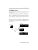
Remote I/O Adapter Module 3 1747-ASB Module Overview The 1747-ASB module is an SLC 500 single-slot, RIO communication link module. It occupies the first slot (slot 0) of a 1746 remote chassis, where the SLC processor normally resides. The 1747-ASB module is an adapter, or slave, on the RIO link, and the master of the remote chassis and remote expansion chassis in which it is installed. Remote expansion chassis are optional.
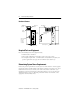
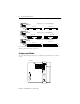
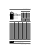
Remote I/O Adapter Module Hardware Features DIP Switches REMOTE I/O SLC 500 MODULE SA IMPORTANT : INST ALL IN SLOT ZERO OF MODULAR CHASSIS ONL CURRENT REQUIREMENT : 375mA OPERATING TEMPERATURE CODE T3C A, B, C AND D, DIV . 2 F AC 1M LISTED IND. CONT . EQ. FOR HAZ. LOC. A196 Y MADE IN USA KEY CLASS 1, GROUPS SW3 ADDR MODE 1 2 3 4 5 6 7 8 RESP SP MODE UL O N HLS PRL ADAPTER SER FRN RET LAST CHA NO.
Remote I/O Adapter Module 5 Slot Addressing Slot Numbering The 1747-ASB module is capable of controlling 30 slots. When expansion chassis are used, the 1747-ASB module treats all of the I/O modules as if they are installed in a single chassis. The remote chassis and remote expansion chassis slots are numbered from 0 to 30. The 1747-ASB module must reside in slot 0. Slots numbered 31 and above cannot be used. IMPORTANT Installing modules in slot 31 or above results in a module error.
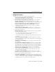
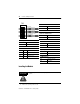
Remote I/O Adapter Module 2-Slot Addressing Two slots are addressed as one logical group. Input Image Output Image Slot Slot 1-Slot Addressing Slot Slot One slot is addressed as one logical group. Input Image Output Image Slot Slot 1/2-Slot Addressing One slot is addressed as two logical groups. Output Image Input Image Slot Slot For more information on addressing, refer to the Remote I/O Adapter Module User Manual, publication number 1747-6.13.
Remote I/O Adapter Module 7 Configuration Parameters The DIP switches allow you to configure the following items: • Starting Logical Rack Number (Logical Rack) - is the 1747-ASB module’s starting logical rack number in the scanner’s image. • Starting Logical Group Number (Logical Group) - is the 1747-ASB module’s starting logical group number within the scanner’s image. • Baud Rate (Baud Rate) - is the 1747-ASB module’s RIO link communication rate.
Remote I/O Adapter Module Dip Switch Settings SW1 Local Rack Number O N 1 2 3 4 Logical Rack Number Bit 5 (Most Significant Bit) ON = 0 Logical Rack Number Bit 4 Logical Rack Number Bit 3 OFF = 1 Local Group Number 5 6 Logical Rack Number Bit 2 Logical Rack Number Bit 1 Logical Rack Number Bit 0 (LSB) 7 8 Logical Group Number Bit 1 (MSB) Logical Group Number Bit 0 (Least Significant Bit) 7 8 Group ON ON 0 (default) ON OFF 2 OFF ON 4 OFF OFF 6 The ASB module can be configured
Remote I/O Adapter Module SW2 9 Baud Rate O N 1 2 3 4 Baud Rate Bit 1 (MSB) SW2-1 SW2-2 Baud Rate 57.6K (default) 5 6 ON ON Primary/Complementary Chassis ON OFF 115.2K Reserved ASB Module Image Size Bit 3 (MSB) OFF ON 230.
Remote I/O Adapter Module SW3 Hold Last State O N 1 2 3 4 Hold Last State ON Hold Last State Processor Restart Lockout Link Response OFF Do not Hold Last State (default) 5 6 Last Chassis/PLC-3 Backup Addressing Mode Bit 1 (MSB) 7 8 Addressing Mode Bit 0 (LSB) Specialty I/O Mode I/O Module Keying Processor Restart Lockout (after lost communications) ON Automatic Restart (default) OFF Processor Lockout Link Response ON Restricted (default) OFF Unrestricted Last Chassis ON Not Last
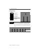
Remote I/O Adapter Module 11 2. Install the module in slot 0 of the remote chassis by aligning the circuit board with the chassis card guide. The 1747-ASB module must be installed only in slot 0 (the left slot) of the remote chassis. Do not install the 1747-ASB module in the remote expansion chassis. 3. Slide the module into the chassis until the top and bottom tabs lock into place. To remove the module, press and hold the release located on each self-locking tab and slide the module out. 4.
Remote I/O Adapter Module There are no restrictions governing the spacing between the devices, as long as the maximum cable distance is not exceeded. Refer to the table on page 18 for baud rate and maximum cable distances. IMPORTANT No two devices can be connected to the same point on the link. An example of correct and incorrect link wiring is shown below.
Remote I/O Adapter Module 13 Link Termination A 6-pin keyed connector provides a quick connection to the RIO link and processor restart lockout switch. A user-supplied terminating resistor must be attached across lines one and two of the connector at each end of the RIO link. The size of the resistor depends on the baud rate and whether the scanner and all adapters have extended node capability, as shown in the table below.
Remote I/O Adapter Module Wiring a Processor Restart Lockout Switch When processor restart lockout is enabled (SW3-2) and communications are restored, the 1747-ASB module does not respond to any type of communication, or communication commands until terminals IN and RET are momentarily shorted together. This occurs while the RIO scanner is attempting to communicate with the 1747-ASB module.
Remote I/O Adapter Module 15 Installing I/O Module Addressing Labels Attach the Remote PLC or Remote SLC label to the outside bottom of each I/O module in your 1747-ASB chassis, as shown below. Fill out each label completely.
Remote I/O Adapter Module Installing Octal Labels The octal filter and door label kits must be used when working with a PLC processor as a master. Adhere the octal labels over the existing decimal labels, as shown below. Contact your local Allen-Bradley distributor if you need to order additional label kits.
Remote I/O Adapter Module 17 Performing System Start-up ATTENTION Never insert, remove, or wire modules with power applied to the chassis or devices wired to the module. ! Follow the steps below: 1. Cycle power one last time in save mode (SW3-8 ON). 2. Remove power from the system. 3. Remove the 1747-ASB module and set SW3-8 to the OFF position (check mode). 4. Replace the 1747-ASB module in slot 0. 5. Apply power to your system.
Remote I/O Adapter Module Specifications Adapter Operating Specifications Backplane Current Consumption 375 mA at 5V dc Operating Temperature 32°F to 140°F (0°C to 60°C) Storage Temperature -40°F to +185°F (-40°C to +85°C) Humidity 5% to 95% non-condensing Noise Immunity NEMA standard ICS 2-230 Vibration Displacement: 0.015 inch, peak-to-peak at 5-57 Hz Shock (operating) 30Gs Acceleration: 2.
Remote I/O Adapter Module 19 For More Information For Refer to this Document Pub. No. A more detailed description on how to install and use Remote I/O Adapter Module your Remote I/O Adapter Module. User Manual 1747-6.13 A more detailed description on how to install and use Remote I/O Scanner Module your Remote I/O Scanner Module (1747-SN). User Manual 1747-6.
Rockwell Automation Support Rockwell Automation provides technical information on the Web to assist you in using its products. At http://support.rockwellautomation.com, you can find technical manuals, a knowledge base of FAQs, technical and application notes, sample code and links to software service packs, and a MySupport feature that you can customize to make the best use of these tools.