Installation Instructions SLC 500 EtherNet/IP Adapter Catalog Number 1747-AENTR Topic Page Important User Information 2 North American Hazardous Location Approval 4 Additional Resources 5 Overview 5 Install the Adapter Module in the Chassis 9 Connect Your Adapter to the Ethernet/IP Network through RJ-45 Connection 10 Troubleshoot with Status Indicators and Status Display 11 Specifications 15
SLC 500 EtherNet/IP Adapter Important User Information Solid-state equipment has operational characteristics differing from those of electromechanical equipment. Safety Guidelines for the Application, Installation and Maintenance of Solid State Controls (publication SGI-1.1 available from your local Rockwell Automation sales office or online at http://www.rockwellautomation.com/literature/) describes some important differences between solid-state equipment and hard-wired electromechanical devices.
SLC 500 EtherNet/IP Adapter 3 Environment and Enclosure ATTENTION: This equipment is intended for use in a Pollution Degree 2 industrial environment, in overvoltage Category II applications (as defined in IEC 60664-1), at altitudes up to 2000 m (6562 ft) without derating. This equipment is considered Group 1, Class A industrial equipment according to IEC/CISPR 11.
SLC 500 EtherNet/IP Adapter North American Hazardous Location Approval The 1747-AENTR module is North American Hazardous Location approved. The following information applies when operating this equipment in hazardous locations: Informations sur l’utilisation de cet équipement en environnements dangereux: Products marked "CL I, DIV 2, GP A, B, C, D" are suitable for use in Class I Division 2 Groups A, B, C, D, Hazardous Locations and nonhazardous locations only.
SLC 500 EtherNet/IP Adapter 5 ATTENTION: Electrostatic discharge can damage semiconductor devices inside the module. Do not touch the connector pins or other sensitive areas. ATTENTION: This equipment must be powered from Allen-Bradley power supply models 1746-P1, 1746-P2, 1746-P3, 1746-P4, 1746-P5, 1746-P6, or 1746-P7. Do not use the 1746-P4 device in UL Class 1, Division 2, Hazardous Locations.
SLC 500 EtherNet/IP Adapter The 1747-AENTR adapter features : • One exclusive owner connection per SLC module (the ability to connect to partial sets of I/O and rack connections are not supported on firmware revision 1.001) • • • • Up to 5 Input Only connections per module Up to 5 Listen Only connections per module Up to 5 explicit messaging connections to the adapter Up to 5 consumers per multicast connection On firmware revision 2.
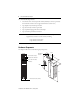
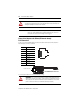
SLC 500 EtherNet/IP Adapter 45846 45845 Left side view Ethernet connectors (RJ-45) 7 Right side view 1 8 8 1 Bottom view 45844 Diagnostic Indicators Health indicators are located on the front panel of the adapter module. They indicate both normal operation and error conditions in your remote I/O system. An alphanumeric display (net address/status) provides status code indications when an error occurs during initialization or operation.
SLC 500 EtherNet/IP Adapter Set the Network Address The network address switches are set to 999 and DHCP enabled, by default. You can set the network Internet Protocol (IP) address in the following ways: • Use the network address switches on the module. • Use a Dynamic Host Configuration Protocol (DHCP) server, such as Rockwell Automation BootP/DHCP. • Retrieve the IP address from nonvolatile memory.
SLC 500 EtherNet/IP Adapter TIP 9 Rockwell Automation recommends that you check or enable the option “Major Fault On Controller If Connection Fails While in Run Mode” on both the 1747-AENTR device and supported 1746 I/O modules. For a step-by-step guide on how to configure your adapter module through the RSLogix 5000 or Logix Designer application, see the User Manual for the SLC 500 EtherNet/IP Adapter, publication 1747-UM076.
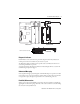
SLC 500 EtherNet/IP Adapter ATTENTION: Do not force the module into the backplane connector. If you cannot seat the module with firm pressure, check the alignment. Forcing the module can damage the backplane connector or the module. IMPORTANT The 1747-AENTR device should always be installed in Slot 0. There should only be one 1747-AENTR device installed within the same rack or its connected rack extensions for multiple chassis support.
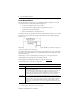
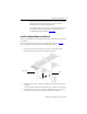
SLC 500 EtherNet/IP Adapter 11 1. Attach the cables with the RJ-45 connectors to the two Ethernet ports on the bottom of the module. 2. Attach the other end of the cables to the devices in your network. IMPORTANT For information on how to install systems with rack extensions, you can refer to the SLC 500 Modular Hardware Style User Manual, publication 1747-UM011. Troubleshoot with Status Indicators and Status Display The module has indicators on the front panel as shown below.
SLC 500 EtherNet/IP Adapter Interpret the Status Indicators Indicator State Description Module Off No power applied to device Green Device operating normally Flashing green Device has not been configured Flashing red Recoverable fault. • IP Address switches do not match configuration in use. • The device has completed a reset to factory default request because the switches were set to 888 at powerup, and a power cycle is required. • The device is performing a firmware flash update.
SLC 500 EtherNet/IP Adapter 13 Four-character Status Display MOD LED Display Description Probable Cause Recommended Action Flashing Red “OK” alternates with the message: “Factory Defaults Restored. Change Address Switches and Reset.” Factory defaults restored Node switches have been set to 888. The AENTR remains in this mode until the switches are changed. Power off the adapter. Remove the adapter from the chassis. Change the node address switch to something other than 888.
SLC 500 EtherNet/IP Adapter Four-character Status Display MOD LED Display Description Probable Cause Recommended Action Solid green Module is communicating and working properly. None None Solid Red “0001” Fatal error The adapter has failed a hardware test, discovered too many I/O racks (greater than 3), or reached a state from which it cannot recover. Verify the correct number of I/O racks and power cycle the adapter. Contact Technical Support if problem persists.
SLC 500 EtherNet/IP Adapter 15 Specifications Ethernet Communication Attribute Value EtherNet communication rate 10/100 Mbits/s, half or full-duplex Ethernet ports 2, configured as Embedded Switch Ethernet network topologies supported Star, Tree, Daisy chain/Linear, and Ring Ethernet connector RJ-45, Category 5 Ethernet cable Category 5: shielded or unshielded General Specifications Attribute Value Module location Always at Slot 0 (leftmost slot) on chassis Current consumption, backplane
SLC 500 EtherNet/IP Adapter Environmental Specifications Attribute Value Temperature, operating IEC 60068-2-1 (Test Ad, Operating Cold), IEC 60068-2-2 (Test Bd, Operating Dry Heat), IEC 60068-2-14 (Test Nb, Operating Thermal Shock): 0…60 °C (32…140 °F) Temperature, nonoperating IEC 60068-2-1 (Test Ab, Unpackaged Non-operating Cold), IEC 60068-2-2 (Test Bb, Unpackaged Non-operating Dry Heat), IEC 60068-2-14 (Test Na, Unpackaged Non-operating Thermal Shock): -40…85 °C (-40…185 °F) Temperature, surr
SLC 500 EtherNet/IP Adapter 17 Certifications Certification (when product is marked)(1) Value c-UL-us UL Listed Industrial Control Equipment, certified for US and Canada. See UL File E322657. UL Listed for Class I, Division 2 Group A, B, C, D Hazardous Locations, certified for U.S. and Canada. See UL File E334470. CE European Union 2004/108/EC EMC Directive, compliant with: EN 61326-1; Meas./Control/Lab.
SLC 500 EtherNet/IP Adapter Notes: Publication 1747-IN521B-EN-E - January 2013
SLC 500 EtherNet/IP Adapter 19 Publication 1747-IN521B-EN-E - January 2013
Rockwell Automation Support Rockwell Automation provides technical information on the Web to assist you in using its products. At http://www.rockwellautomation.com/support/, you can find technical manuals, a knowledge base of FAQs, technical and application notes, sample code and links to software service packs, and a MySupport feature that you can customize to make the best use of these tools.