
User Manual


28 Rockwell Automation Publication 1747-UM076C-EN-E - January 2013
28 Configure the Adapter for Direct Connection through the RSLogix 5000 or Logix Designer Application
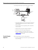
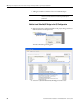
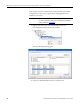
To work along with this example, set up your system as shown in the figure.
• In the example application, we assume that the Logix5575 controller and
1756-EN2TR module (firmware revision 3.1, or later) are in the slots
shown in the figure.
• Verify the IP addresses for your programming terminal, 1756-EN2TR
module, and adapter.
• Verify the position (slot) of the I/O modules on the DIN rail.
• Verify that you connected all wiring and cabling properly.
• Be sure you configured your communication driver (for example,
AB_ETH-1 or AB-ETHIP-1) in RSLinx software, as described in the
Appendix
on page 71 of this manual.
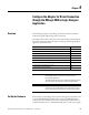
Create the Example
Application
Perform the following steps to create the example application:
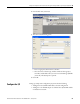
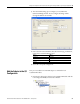
1. Start RSLogix 5000 Enterprise Series software to open the RSLogix 5000
software main dialog.
Local
chassis
Logix5575
controller (slot 1)
1756-EN2TR
10.88.70.4 (slot 3)
Data
Switch
10.88.70.26
Programming
terminal
Slot 0 1 2 3
1747-AENTR
10.88.70.2
tolS 0123
45176
1746-IO8
1746-IA4
1746-BAS/B