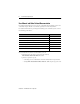
Installation Instructions ControlNet Adapter Module 1747-ACN15, 1747-ACNR15 What This Document Describes For information on: Refer to page: Additional Documentation 2 Module Description and Features 4 Hardware Components 4 Determining Power Requirements 6 Installing the Adapter Module 7 Connecting Programming Terminals 12 Powerup Sequence 13 Troubleshooting 14 ControlNet Status Indicators 16 Specifications 19 Publication 1747-IN017C-EN-P - May 2001
ControlNet Adapter Module User Manual and Other Related Documentation For detailed information on how to use the ControlNet Adapter Module, refer to the ControlNet Adapter Module User Manual, publication 1747-UM003A-EN-P. For detailed information on planning and installing your ControlNet system, refer to the following publications: Publication Publication Number ControlNet Adapter User Manual 1747-UM003A-EN-P ControlNet Cable System Component List AG-2.
ControlNet Adapter Module 3 European Communities (EC) Directive Compliance If this product has the CE mark it is approved for installation within the European Union and EEA regions. It has been designed and tested to meet the following directives.
ControlNet Adapter Module Module Description and Features The 1747-ACN15 and -ACNR15 adapters control 1746 remote I/O on the ControlNet network. The ControlNet network is a communication architecture that allows the exchange of messages between ControlNet products compliant with the CI specification. The adapters support multiple scheduled connections to individual modules or rack scheduled connections to a group of modules.
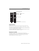
ControlNet Adapter Module 5 Module Network Address Switches (accessible through top of module) ADDRESS/STATUS OK A ADDRESS/STATUS B OK A Status Display and Net Address Diagnostic Indicators Health Indicators ControlNet Status Indicators Network Access Port (NAP) A 1747-ACN15 B A ControlNet Media Port (A) ControlNet Redundant Media Port (B) (1747-ACNR15 only) 1747-ACNR15 Diagnostic Indicators Health indicators are located on the front panel of the adapter module.
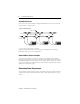
ControlNet Adapter Module ControlNet Connectors Cable connection to the module is through standard BNC connectors on the front of the module, as shown below. . Example of a Redundant System trunkline A = A Terminator trunkline B = B Terminator SLC 5/02 or later with 1747-SCNR end device1 1. End device supporting redundant cabling is a 1747-ACNR15. Refer to the ControlNet Cable System Planning and Installation User Manual, Publication 1786-6.2.1 for more information.
ControlNet Adapter Module 7 Setting the Network Address Switches The switches on the top of the adapter module determine the network address of the adapter. The two switches are: • the ten’s switch • the one’s switch The combination of these switches allows selection of network addresses from 01 to 99. Ten’s Selection TIP One’s Selection 00 is an invalid number.
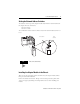
ControlNet Adapter Module WARNING ! If you insert or remove the ControlNet Adapter with power applied to this module or any device on the network, an electrical arc can occur. This could cause an explosion in hazardous location installations. Be sure that power is removed or the area is nonhazardous before proceeding. 1. Remove power from the I/O chassis before inserting (or removing) the module. 2. Align the circuit board with the chassis card guide in the left slot.
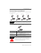
ControlNet Adapter Module 9 Connecting Your Adapter to the ControlNet Network Connect your 1747-ACN15 or -ACNR15 adapter module to a ControlNet network via taps. as shown below: Straight T-tap 1766-TPS IMPORTANT Straight Y-tap 1786-TPYS Right-angle T-tap 1786-TPR Right-angle Y-tap 1786-TPYR Taps contain passive electronics and must be purchased from Rockwell Automation for the network to function properly. 1. Remove the tap’s dust cap (located on the straight or right angle connector).
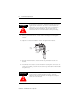
ControlNet Adapter Module 2. Remove and discard the dust caps from the adapter BNC jacks. segment 1 Tap dust cap ATTENTION ! Do not allow any metal portions of the tap to contact any conductive material. If you disconnect the tap from the adapter, place the dust cap back on the straight or right angle connector to prevent the connector from accidentally contacting a metallic grounded surface. segment 1 Tap dust cap 3. Remove and discard the dust caps from the adapter BNC jacks. 4.
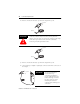
ControlNet Adapter Module 11 5. For redundant adapters (1747-ACNR15), remove (and save) the dust cap located on the straight or right angle connector of the designated tap on the second segment (segment 2). segment 2 tap dust cap 6. Connect this tap’s straight or right angle connector to the BNC connector on the adapter. segment 2 segment 1 tap tap 7. After terminating your segments, connect the node to the network.
ControlNet Adapter Module Connecting Programming Terminals to the Network via the NAP You can connect programming terminals to the ControlNet network by connecting to the network access port (NAP). Two methods are shown below.
ControlNet Adapter Module 13 Powerup Sequence There are three health indicators on the module. The indicator on the right (labeled “OK”) is the general module health indicator. The indicator in the middle (labeled “A”) is the health indicator for cable A. On the 1747-ACNR15, the indicator on the left (labeled “B”) is the health indicator for cable B. Also, the alphanumeric display can display module status. The following describes the normal power-up sequence for the adapter module.
ControlNet Adapter Module Troubleshooting With the Status Indicators and Status Display The module has indicators on the front panel as shown below. These indicators consist of: • health indicators • status indicators • display of status and address Use these indicators to troubleshoot the module.
ControlNet Adapter Module OK LED Display Solid Red FATL Number Module is not Number communicating. Description 15 Probable Cause Recommended Action The adapter has either failed a hardware test, or gone into a state from which it cannot recover. The two numbers following the FATL describe the problem in detail. Document the two numbers. Power cycle the adapter. Contact Technical Support at 440.646.6800. Flashing Red A#00 ERR Module is not communicating.
ControlNet Adapter Module ControlNet Status Indicators • steady - indicator is on continuously in the defined state. • alternating - the two indicators alternate between the two defined states at the same time (applies to both indicators viewed together). The two indicators are always in opposite states, out of phase. • flashing - the indicator alternates between the two defined states (applies to each indicator viewed independent of the other).
ControlNet Adapter Module 17 The following information applies when operating this equipment in hazardous locations: Products marked “CL I, DIV 2, GP A, B, C, D” are suitable for use in Class I Division 2 Groups A, B, C, D, Hazardous Locations and nonhazardous locations only. Each product is supplied with markings on the rating nameplate indicating the hazardous location temperature code.
ControlNet Adapter Module Informations sur l’utilisation de cet équipement en environnements dangereux : Les produits marqués « CL I, DIV 2, GP A, B, C, D » ne conviennent qu’à une utilisation en environnements de Classe I Division 2 Groupes A, B, C, D dangereux et non dangereux. Chaque produit est livré avec des marquages sur sa plaque d’identification qui indiquent le code de température pour les environnements dangereux.
ControlNet Adapter Module 19 Specifications Description Specification Module Location 1746 I/O chassis, leftmost slot Interconnect Cable Quad shield RG-6 coaxial cable - Refer to the ControlNet Cable System manual (pub. no. 1786-6.2.1) for more information Power Dissipation 5 Watts Thermal Dissipation 17.
Publication 1747-IN017C-EN-P - May 2001 Supersedes Publication 1747-IN017B-EN-P - May 2001 PN 957564-04 © 2001 Rockwell Automation. Printed in the U.S.A.