
User Manual

SLC™ 500 4-Channel Analog I/O Modules 5
Publication 1746-IN008C-EN-P - May 2004
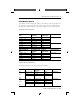
Analog Modules Operation
The module converts analog input signals to 16-bit binary values for storage in the
SLC processor’s input image table. The decimal range, number of significant bits,
and converter resolution depend on the input range that you use for the channel.
Analog Input A/D Characteristics
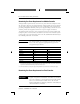
Analog Output D/A Characteristics
The analog modules have the same output characteristics.
NI4, NIO4I, & NIO4V Input
Range
Decimal Range (input
image table)
Number of
Significant Bits
Nominal Resolution
±10V dc -1 LSB -32,768 to +32,767 16 305.176 µV/LSB
0 to 10V dc -1 LSB 0 to 32,767 15
0 to 5V dc 0 to 16,384 14
1 to 5V dc 3,277 to 16,384 13.67
±20 mA ±16,384 15 1.22070 µA/LSB
0 to 20 mA 0 to 16,384 14
4 to 20 mA 3,277 to 16,384 13.67
FIO4I and FIO4V Input
Range
Decimal Range (input
image table)
Number of
Significant Bits
Nominal Resolution
0 to 10V dc -1 LSB 0 to 4095 12 2.4414 mV/LSB
0 to 5V dc 0 to 2047 11
1 to 5V dc 409 to 2047 10.67
0 to 20 mA 0 to 2047 11 9.7656 µA/LSB
4 to 20 mA 409 to 2047 10.67
Module Output Range Decimal Range (output
image table)
Significant Bits Resolution
FIO4I
NIO4I
NO4I
0 to 21 mA - 1 LSB 0 to 32,764 13 bits 2.56348 µA/LSB
0 to 20 mA 0 to 31,208 12.92 bits
4 to 20 mA 6,242 to 31,2089 12.6 bits
FIO4V
NIO4V
NO4V
±10V dc - 1 LSB -32,768 to +32,764 14 bits 1.22070 mV/LSB
0 to 10V dc -1 LSB 0 to 32,764 13 bits
0 to 5V dc 0 to 16,384 12 bits
1 to 5V dc 3,277 to 16,384 11.67 bits
@JO$&/QQE@JO$&/QQE ".".