Installation Instructions SLC™ 500 4-Channel Analog I/O Modules (Catalog Numbers 1746-NI4, -NIO4I, -NIO4V, -NO4I, -NO4V, -FIO4I, and -FIO4V) Inside… ........................................................................................... page Important User Information ...................................................................... 2 For More Information ............................................................................. 3 Types of Analog Modules.......................................
SLC™ 500 4-Channel Analog I/O Modules Important User Information Solid state equipment has operational characteristics differing from those of electromechanical equipment. Safety Guidelines for the Application, Installation and Maintenance of Solid State Controls (Publication SGI-1.1 available from your local Rockwell Automation sales office or online at http://www.ab.com/manuals/gi) describes some important differences between solid state equipment and hard-wired electromechanical devices.
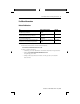
SLC™ 500 4-Channel Analog I/O Modules 3 For More Information Related Publications For Refer to this Document Pub. No. A more detailed description on how to configure the SLC 500 Analog I/O Modules. SLC 500 Analog I/O Modules User Manual 1746-UM005 A more detailed description on how to install and integrate SLC 500 Fast Analog I/O Modules. SLC 500 Fast Analog I/O Modules User Manual 1746-6.
SLC™ 500 4-Channel Analog I/O Modules Types of Analog Modules 1746-NI4 Analog Input Module The NI4 Analog Input module contains 4 analog input channels that are user selectable per channel for voltage or current to support a variety of monitoring and controlling applications. 1746-NO4I and NO4V Analog Output Modules The NO4I and NO4V Analog Output Modules provide 4 analog output channels. The NO4I module contains 4 current outputs. The NO4V module contains 4 voltage outputs.
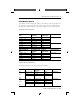
SLC™ 500 4-Channel Analog I/O Modules 5 Analog Modules Operation The module converts analog input signals to 16-bit binary values for storage in the SLC processor’s input image table. The decimal range, number of significant bits, and converter resolution depend on the input range that you use for the channel. Analog Input A/D Characteristics NI4, NIO4I, & NIO4V Input Range Decimal Range (input image table) Number of Significant Bits Nominal Resolution ±10V dc -1 LSB -32,768 to +32,767 16 305.
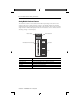
SLC™ 500 4-Channel Analog I/O Modules Analog Module Hardware Features The module contains a removable terminal block providing connection for the analog input and/or output channels, which is specifically designed to interface with analog current and voltage input signals. The channels can be wired as either single-ended or differential inputs. There are DIP switches on the circuit board for selecting voltage or current input.
SLC™ 500 4-Channel Analog I/O Modules 7 Hazardous Location Considerations This equipment is suitable for use in Class I, Division 2, Groups A, B, C, D or non-hazardous locations only. The following WARNING statement applies to use in hazardous locations. WARNING EXPLOSION HAZARD • Substitution of components may impair suitability for Class I, Division 2. • Do not replace components or disconnect equipment unless power has been switched off.
SLC™ 500 4-Channel Analog I/O Modules Determining Your Power Requirements for a Modular Controller Analog modules require both 5V dc and 24V dc power from the backplane of the SLC 500 system. However, the NO4I and NO4V analog modules can use an external 24V dc power supply. This eliminates the 24V dc backplane power requirements, providing configuration flexibility if SLC power supply loading is critical. These two modules provide user-supplied external 24V dc power supply connections.
SLC™ 500 4-Channel Analog I/O Modules 9 Configuring Your Module The NI4, NIO4I, NIO4V, FIO4I, and FIO4V analog modules have user-selectable DIP switch settings, which allow you to configure the input channels as either current or voltage inputs. The switches are located on the analog module board. The following illustration shows the ON and OFF switch settings. Switch orientation is also provided on the nameplate of the module.
SLC™ 500 4-Channel Analog I/O Modules Switch Settings for the 1746-NIO4I, -NIO4V, -FIO4I, and -FIO4V The NIO4I and NIO4V have 2 individual switches labeled 1 and 2. These switches control the input mode of channel 0 and 1. A switch in the ON position configures the channel for current input. A switch in the OFF position configures the channel for voltage input.
SLC™ 500 4-Channel Analog I/O Modules 11 Installing Your Module All modules are mounted in a single slot. Remember that in a modular system the processor always occupies the first slot of the first chassis. ATTENTION Never install, remove, or wire modules with power applied to the chassis. Also, do not expose analog modules to surfaces or other areas that may typically hold an electrostatic charge. Electrostatic charges can destroy the analog circuitry.
SLC™ 500 4-Channel Analog I/O Modules Top and Bottom Module Release (s) Card Guide Wiring Considerations The following section provides system wiring guidelines, how to ground your Belden™ cable, and how to determine the cable length. ATTENTION Before wiring any analog module, disconnect power from the SLC 500 system and from any other source to the analog module. Publication 1746-IN008C-EN-P - May 2004 @ JO $ &/ Q QE ".
SLC™ 500 4-Channel Analog I/O Modules 13 System Wiring Guidelines Use the following guidelines in planning the system wiring for the analog modules: • all analog common terminals (ANL COM) are electrically connected inside the module. ANL COM is not connected to earth ground inside the module. • voltages on IN+ and IN- terminals must remain within ± 20 Volts with respect to ANL COM to ensure proper input channel operation. This is true for current and voltage input channel operation.
SLC™ 500 4-Channel Analog I/O Modules Belden Cable #8761 Foil Shield Black Wire Clear Wire Drain Wire Determining the Cable Length Determine the length of cable you will need to connect a channel to its input or output device. Remember to leave additional length to route the drain wire and foil shield for earth grounding. Wiring the Analog Module After the analog module is properly installed in the chassis, use the following wiring procedure.
SLC™ 500 4-Channel Analog I/O Modules 15 4. At END 1, twist the drain wire and foil shield together, bend them away from the cable, and apply shrink wrap. 5. At END 2, cut the drain wire and foil shield back to the cable and apply shrink wrap. 6. Connect the signal wires (black and clear) to the terminal block and the input and output devices. The recommended maximum torque is 0.57 Nm (5 lb-in) for all terminals. • Input channels - connect END 1 at module.
SLC™ 500 4-Channel Analog I/O Modules Labeling and Installing the Terminal Block The terminal block has a write-on label. Labeling the terminal block will help ensure that it is installed on the correct module. When installing the analog module in a chassis, it is not necessary to remove the terminal block from the module. However, if the terminal block is removed, use the write–on label located on the side of the terminal block to identify the module location and type.
SLC™ 500 4-Channel Analog I/O Modules 17 Minimizing Electrical Noise on Analog Modules Inputs on analog modules employ digital high frequency filters that significantly reduce the effects of electrical noise on input signals. However, because of the variety of applications and environments where analog modules are installed and operating, it is impossible to ensure that all environmental noise will be removed by the input filters.
SLC™ 500 4-Channel Analog I/O Modules Wiring Diagram (showing differential inputs) NI4 + analog source - earth ground + analog source - earth ground Jumper unused inputs. NIO4I, NIO4V, FIO4I, and FIO4V 0 1 2 3 4 5 6 7 8 9 10 11 IN 0+ IN 0ANL COM IN 1+ IN 1ANL COM 0 1 2 3 4 5 6 7 8 9 10 11 IN 0+ IN 0ANL COM IN 1+ IN 1ANL COM IN 2+ IN 2ANL COM IN 3+ IN 3ANL COM + analog source - earth ground Jumper unused inputs.
SLC™ 500 4-Channel Analog I/O Modules ATTENTION 19 Any individual single-ended input device can be connected to any single differential input shown on page 18. The single-ended input common is connected to the negative differential input point. Wiring Schematics for 2, 3, and 4-Wire Analog Input Devices IMPORTANT The module does not provide loop power for analog inputs. Use a power supply that matches the transmitter specifications.
SLC™ 500 4-Channel Analog I/O Modules Wiring Schematic for Single-Ended Analog Input Connections When wiring single-ended analog input devices to the analog input card, the number of total wires necessary can be limited by using the ANALOG COMMON terminal. Note that differential inputs are more immune to noise than single-ended inputs.
SLC™ 500 4-Channel Analog I/O Modules 21 Specifications General Specifications for NI4, NIO4I, NIO4V, NO4I, NO4V, FIO4I, FIO4V Description Specification SLC Communication Format 16-Bit Two’s Complement Binary Field Wiring to Backplane Isolation 500V dc Update Time 512 µs for all channels in parallel Recommended Cable Shielded Belden #8761 Maximum Wire Size #14 AWG (maximum) Terminal Block Removable Location 1746 chassis Calibration Factory Calibrated (1) Noise Immunity NEMA Standard ICS
SLC™ 500 4-Channel Analog I/O Modules Backplane Current Specification for NI4, NIO4I, NIO4V, NO4I, NO4V, FIo4I, and FIO4V Catalog 1746- Input Channels per Output Module Channels per Module Backplane Current Draw 5V (max.) 24V (max.
SLC™ 500 4-Channel Analog I/O Modules 23 General Analog Input Specifications for NI4, NIO4I, NIO4V, FIO4I, and FIO4V Description Specification NI4 NIO4I, NIO4V FIO4I, FIO4V Converter Resolution 16-Bit Repeatability ±1 LSB 12-bit Location of LSB in I/O image word 0000 0000 0000 0001 Non-linearity 0.01% ±0.073% of full scale max. Common Mode Voltage Range -20 to +20 volts 0 to +20 Volts (max) Common Mode Rejection at 0 to 10 Hz (min.) 50 dB Common Mode Rejection at 60 Hz (min.
SLC™ 500 4-Channel Analog I/O Modules Current-Loop Input Specifications for NI4, NIO4I, NIO4V, FIO4I, and FIO4V Description Specification NI4, NIO4I, NIO4V FIO4I, FIO4V Input Range (Normal Operation) -20 to +20 mA 0 to 20 mA (nominal) Absolute Maximum Input Current -30 to +30 mA 0 to 30 mA (maximum) Absolute Maximum Input Voltage ±7.5V dc or 7.5V ac RMS Current Input Coding -20 to +20 mA -16,384 to +16,384 Input Impedance 250 Ohms Resolution 1.
SLC™ 500 4-Channel Analog I/O Modules 25 Voltage Input Specifications for NI4, NIO4I, NIO4V, FIO4I, and FIO4V Description Specification NI4 Input Range NIO4I, NIO4V -10 to +10V dc - 1 LSB 0 to +10V dc Voltage Input Coding (-10 to +10V dc - 1 -32,768 to +32,767 LSB) Input Impedance 760K ohms(1) Resolution 305.176 µV per LSB Full Scale 10V dc FIO4I, FIO4V 0 to +4095 1M ohms 2.4414 mV per LSB Overall Accuracy at +25° C (77° F) (max.) ±0.284% of full scale ±0.
SLC™ 500 4-Channel Analog I/O Modules Current Output Specifications for NIO4I, NO4I, and FIO4I Description Specification NIO4I, NO4I FIO4I Converter Resolution 14 bit Location of LSB in I/O image word 0000 0000 0000 01XX Non–linearity 0.05% Conversion Method R-2R Ladder Step Response 2.
SLC™ 500 4-Channel Analog I/O Modules 27 Voltage Output Specifications for NIO4V, NO4V, and FIO4V Description Specification NIO4V and NO4V FIO4V Converter Resolution 14 bit Location of LSB in I/O image word 0000 0000 0000 01XX Non-linearity 0.05%of full scale Conversion Method R-2R Ladder Step Response 2.5 ms (at 95%) 2.
Rockwell Automation Support Rockwell Automation provides technical information on the web to assist you in using our products. At http://support.rockwellautomation.com, you can find technical manuals, a knowledge base of FAQs, technical and application notes, sample code and links to software service packs, and a MySupport feature that you can customize to make the best use of these tools.