Installation Instructions SLC 500™ 32-Channel Digital I/O Modules (Catalog Numbers 1746-IB32, -IV32, -OB32, -OB32E and -OV32) Important User Information ........................................................... 2 Hazardous Location Considerations .............................................. 3 Environnements dangereux ........................................................... 3 Overview ........................................................................................
SLC 500™ 32-Channel Digital I/O Modules Important User Information Because of the variety of uses for the products described in this publication, those responsible for the application and use of these products must satisfy themselves that all necessary steps have been taken to assure that each application and use meets all performance and safety requirements, including any applicable laws, regulations, codes and standards.
SLC 500™ 32-Channel Digital I/O Modules 3 Hazardous Location Considerations This equipment is suitable for use in Class I, Division 2, Groups A, B, C, D or non-hazardous locations only. The following WARNING statement applies to use in hazardous locations. WARNING ! EXPLOSION HAZARD • Substitution of components may impair suitability for Class I, Division 2. • Do not replace components or disconnect equipment unless power has been switched off or the area is known to be non-hazardous.
SLC 500™ 32-Channel Digital I/O Modules Overview In addition to providing the module’s electrical specifications, this document tells you how to: • install the module into the chassis • install the Octal Filter Label • wire the module We assume you have already installed your chassis and power supply. If not, please refer to the installation instructions for these products before preceding.
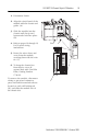
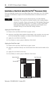
SLC 500™ 32-Channel Digital I/O Modules 5 1. Disconnect Power 2. Align the circuit board of the module with the chassis card guide. (A) 3. Slide the module into the chassis until the tip and bottom tabs lock into place. (B) 4. Refer to pages 16 through 19 for 32-point wiring instructions. B D Slot 1 A 5. Route the wires down and away from the module, securing them with the wire tie. (C) 6. To keep the chassis free from debris, cover all unused slots with Card Slot Filler, Catalog Number 1746-N2.
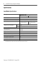
SLC 500™ 32-Channel Digital I/O Modules Specifications Input Module Specifications Description: Specification: 1746-(1) IB32 Voltage Category 24 Number of Inputs 32 Points per Common 8 Operating Voltage 15 to 30V dc at 50° C 15 to 26.4V dc at 60° C Sink Backplane Current Consumption 5V 0.050A 24V 0A Isolation from Backplane 1500V ac for 1 min. Signal Delay (max.) on = 3 ms off = 3 ms On State Voltage (min.) 15.0V dc Off State Voltage (max.) 5.0V dc Off State Current (max.) 1.
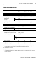
SLC 500™ 32-Channel Digital I/O Modules 7 Output Module Specifications Description: Specification: 1746-(4) OB32 Series D Voltage Category 24 Number of Outputs 32 Points per Common 16 Operating Voltage Backplane Current Consumption 5 to 50V dc Source 5V 0.190A 24V 0A Isolation from Backplane 1500V ac for 1 min. Signal Delay (max.) on = 0.1 ms off = 1.0 ms Off State Leakage (min.) 1 mA Load Current (min.) 1 mA Continuous Current per Module (max.)(1) 8.
SLC 500™ 32-Channel Digital I/O Modules ATTENTION ! A transient pulse occurs in transistor inputs when the external dc supply voltage is applied to the output common terminals (e.g., via the master control relay). This can occur whether or not the processor is powered. For most applications, the energy of this pulse is not sufficient to energize the load.
SLC 500™ 32-Channel Digital I/O Modules 9 Auto Reset Operation IMPORTANT The 1746-OB32E performs auto-reset under overload conditions. When an output channel overload occurs as described above, that channel limits current within milliseconds after its thermal cut-out temperature has been reached.
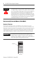
SLC 500™ 32-Channel Digital I/O Modules Installation of the Octal Label Kit (for PLC® Processors Only) The octal label kit consists of an octal filter label and a door label. In a PLC system, use these octal labels to replace the decimal labels that are attached to the I/O modules. TIP The octal label kit can be obtained from your Allen-Bradley Distributor. The octal kit is ordered based on the catalog number of the I/O module.
SLC 500™ 32-Channel Digital I/O Modules 11 Wiring Options for the I/O Module Included with your 32-point I/O module is a keyed 40-pin female connector and crimp type pins. These components allow you to wire I/O devices to the module using a 40-conductor cable or individual wires. The wiring diagrams on pages 16 through 19 show the I/O terminations of the connector for your specific module. Refer to page 15 for connector/pin assembly instructions.
SLC 500™ 32-Channel Digital I/O Modules Option 2 - Using Allen-Bradley 1492 Wiring Systems Allen-Bradley 1492 wiring systems are available for connecting 32 point I/O modules to external I/O. These wiring systems include a pre-wired cable available in four lengths: 0.5m (1.6 feet), 1.0m (3.3 feet), 2.5m (8.2 feet), 5.0m (16.4 feet). An Interface Module for connecting external devices is also available. Cables are equipped with keyed connectors at both ends for proper connections.
SLC 500™ 32-Channel Digital I/O Modules Catalog No. Voltage Drop at 30° C Voltage Drop at 60° C Series C Cables V dc and dc come Output Channel Wires(1) Wires(2) V dc and dc com Wires Output Channel Wires 1492-CABLE005H 127 mv 34 mv 144 mv 38 mv 1492-CABLE10H 173 mv 45 mv 196 mv 51 mv 1492-CABLE25H 334 mv 83 mv 388 mv 95 mv 1492-CABLE50H 574 mv 147 mv 686 mv 169 mv (1) Voltage drop at maximum rated current of 2 amps per conductor.
SLC 500™ 32-Channel Digital I/O Modules Terminal Block Labels Bottom Terminal Block Top Terminal Block 1746-OB32 1746-OV32 1746-IV32 1746-IB32 1746-OB32 1746-OV32 1746-IV32 1746-IB32 SLC PLC SLC PLC SLC PLC SLC PLC SLC PLC SLC PLC +V1 +V1 0 1 2 3 4 5 6 7 8 9 10 11 12 13 14 15 CM1 CM1 +V1 +V1 0 1 2 3 4 5 6 7 10 11 12 13 14 15 16 17 CM1 CM1 +V1 +V1 0 1 2 3 4 5 6 7 8 9 10 11 12 13 14 15 +V2 +V2 +V1 +V1 0 1 2 3 4 5 6 7 10 11 12 13 14 15 16 17 +V2 +V2 CM1 CM1 0 1 2 3 4 5 6 7 8 9 10 1
SLC 500™ 32-Channel Digital I/O Modules 15 Assembling the Wire Contacts 1. Strip the wire insulation as shown in Figure 1. Crimp pins can accept 22 to 26 AWG wire. 2. Insert the wire up to the wire stop as shown in Figure 2. 3. Crimp with DDK crimp tool 357J-5538. Equivalent Amp part numbers are: pin - #87666-2, connector - #102387-9, and crimp tool - #90418-1. Pins and connectors from different manufacturers cannot be assembled together. For example, Amp pins cannot be used with a DDK connector.
SLC 500™ 32-Channel Digital I/O Modules Wiring Diagrams In this document, the wiring diagrams include both decimal and octal numbers. To wire your module when used in an SLC system, use the decimal numbers. To wire your module when used in a PLC system, use the octal numbers.
SLC 500™ 32-Channel Digital I/O Modules 17 Input Module 1746-IV32 (24V dc Sourcing) +V dc 1(2) +V dc 1 Wire Group 3 Wire Group 1 (2) VDC 1 VDC 3 +V dc 3(2) VDC 1 VDC 3 +V dc 3(2) IN 0 dc Com 1 IN 16 IN 17 IN 1 1 1 IN 2 IN 18 2 2 IN 19 IN 3 3 3 IN 20 IN 4 4 4 IN 21 IN 5 5 5 IN 22 IN 6 6 6 IN 23 IN 7 Connector Key 7 7 IN 8 IN 24 10 10 IN 25 IN 9 11 11 IN 26 IN 10 12 12 IN 11 IN 27 13 13 IN 12 IN 28 14 14 IN 29 IN 13 15 15 IN 14 IN 30 16 16 IN 15 dc Com 2 +
SLC 500™ 32-Channel Digital I/O Modules Output Module (1746-OB32 and 1746-OB32E) 1746-OB32 5 to 50V dc Transistor Output Sourcing 1746-OB32E 10 to 30V dc Electronically Protected Sourcing Wire Group 1 +V dc 1(2)(3) Wire Group 2 VDC 1 +V dc 1(2)(3) VDC 1 VDC 2 +V dc 2(2)(3) VDC 2 +V dc 2(2)(3) OUT 16 OUT 0 CR 0 1 2 1 2 CR OUT 19 OUT 3 CR CR CR OUT 18 OUT 2 CR 0 OUT 17 OUT 1 CR 3 3 4 4 OUT 21 OUT 5 5 5 OUT 6 OUT 22 6 6 Connector Key OUT 23 OUT 7 7 7 OUT 24 OUT 8 CR 10
SLC 500™ 32-Channel Digital I/O Modules 19 Output Module 1746-OV32 (5 to 50V dc Transistor Output Sinking) +V dc 1 Wire Group 2 Wire Group 1 (2) VDC 1 +V dc 1(2) VDC 1 +V dc 2(2) VDC 2 +V dc 2(2) OUT 16 OUT 0 CR 0 0 1 1 2 2 3 OUT 4 3 4 4 OUT 21 5 5 OUT 22 OUT 6 6 6 OUT 23 OUT 7 7 7 OUT 24 OUT 8 CR 10 10 OUT 25 OUT 9 11 OUT 10 11 OUT 26 12 12 OUT 27 OUT 11 CR 13 OUT 12 CR CR CR 13 14 14 OUT 29 15 15 OUT 14 OUT 30 16 OUT 15 17 dc Com 1(2)(3) CR OUT 28 OUT 13 dc
For More Information For Refer to this Document Pub. No. A more detailed description on how to install and use your modular SLC 500 system. SLC 500 Modular Hardware Style User Manual 1747-UM011 A reference manual that contains status file data, instruction set, and troubleshooting information.