
QUICK START SYNCHRONIZED AXES Owner's manual

Synchronized Axes Control Module2
Publication
1746-10.3 – December 1997
3.
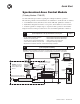
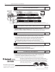
Connect LDT to Interface Module Terminal Block Chapter 2
We give you example LDT connections for a Temposonics II with differential inputs.
+Ret –Ret +Out Out +Ret –Ret +Out Out +Ret –Ret +Out Out +Ret –Ret +Out Out
1 1 1 Com
2 2 2 Com 3 3 3 Com 4 4 4 Com
+Int –Int SH SH
+Int –Int SH SH +Int –Int SH SH +Int –Int SH SH –V +V
1 1 2 2 3 3 4 4
–V LDT +V
–V LDT +V –V LDT +V –V LDT +V PS Earth
1F Com 1F
2F Com 2F 3F Com 3F 4F Com 4F Com GND
Axis Loop 1
Axis Loop 2 Axis Loop 3 Axis Loop 4
16 32 33
50 51
0
12
4 8
20 24 28
34 38 42 46
Internal Connections:
–V (32) is connected to (34) (38) (42) (46) through fuses that you provide
+V (33) is connected to (36) (40) (44) (48) through fuses that you provide
Earth GND (51) is connected to all SH (18) (19) (22) (23) (26) (27) (30) (31)
PS Com (50) is connected to all LDT Com (35) (39) (43) (47)
"
15V
Power
Supply
(– ) (C) (+)
35 36
1
17
10
1
23
4
5
6
7
8
9
(+)
(+)
(–)
(–)
(–)
(+)
Temposonics II,
RPM or DPM
2 3
Drive Output
+
_
18 19
4.
Get Manual, Hydraulic Configurator Software, & Ladder Logic Files from the Internet Chapter 3
Path to the Allen-Bradley website: http://www.ab.com
extension to manual:
/manuals (Application Systems Library, publication 1746-6.19)
extension to Hydraulic Configurator and ladder logic: /mem/appsys/prodinfo/applac/appla/qssw/index.html
Download manual, Hydraulic Configurator, and ladder logic to separate subdirectories in your hard drive.
5.
Set Up Communication Between PC and QS Module Chapter 3
1. Connect the PC serial port (COM1) to the QS module’s 9-pin connector with a 1747-CP3 cable.
You may run RSLogix500 and Hydraulic Configurator softwares if COM1 & 2 are both available,
or if you provide a KTX card for DH+ connection to SLC processor with another 1747-CP3 cable.
2. Open Hydraulic Configurator. Main screen appears. If also “No Motion Controller Detected”, then
check the 1747-CP3 cable connection between PC and QS module, and/or go to step 3.
3. Set Hydraulic Configurator COM port to match your PC. To do this, pull Monitor Options from
T
ools in the ToolBar. In the window, enter the COM port number you used in step 1.
You
can run Hydraulic Configurator of
fline to access help screens, and view stored data
and axis plots.
6.
With Hydraulic Configurator, Set Up and Tune Each Axis Chapter 4
1. Enter the type of LDT in the Configuration word.
2. Determine
the Of
fset and Scale Parameters and the Extend and Retract Limits in open-loop mode.
3. Determine the value of the Dead Band Eliminator.
4. Tune each axis in closed-loop mode, independent of ladder logic.
5. Save configuration parameters for each axis in SLC memory.
7.
Create Ladder Logic to Run Your Application Chapter 5
We provide sample ladder programs to illustrate preferred methods of using the module.
You
may download them from our website and use them as a base for creating your own logic (step
3).
1. Configure I/O for SLC processor: module slot number, ID = 13627, advance config M0 = M1 = 64.
2. If using our logic, modify rungs and addresses to match your system.
3. Integrate synchronized axes movement with ladder logic using status bits and command words.
Allen-Bradley, a Rockwell Automation Business, has been helping its customers improve
productivity and quality for more than 90 years. We design, manufacture and support a broad
range of automation products worldwide. They include logic processors, power and motion
control devices, operator interfaces, sensors and a variety of software. Rockwell is one of the
world’s leading technology companies.
Worldwide representation
Allen-Bradley
Headquarters, 1201 South Second Street, Milwaukee, WI 53204 USA, T
el: (1) 414 382-2000 Fax: (1) 414 382-4444
Publication 1746-10.3 – December 1997
PN955131-08
Copyright
1997 Allen-Bradley Company
, Inc. Printed in USA