
QUICK START SYNCHRONIZED AXES Owner's manual

Publication 1746-10.3 – December 1997
(Catalog Number 1746-QS)
Use this abbreviated procedure for getting the 1746-QS module into operation.
The following software and documentation are available for download from our website:
• User Manual for the Synchronized Axes Control Module, publication 1746-6.19
• Hydraulic Configurator Software to set up, tune, and troubleshoot axis movement
• Ladder Logic File of example logic to sequence module operation to the machine
Chapter references in this procedure refer to the user manual, publication 1746-6.19.
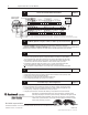
1.
System Requirements for the Synchronized Axes Control System Chapter 1
In addition to the 1746-QS module, you must have (or purchase) the following:
– PC with 4 MByte of available disk space – Interface Module (terminal blk) (1492-AIFMQS)*
– Windows ’95 operating system – Interface Module cable (1492-ACABLExxxQS)*
– SLC 5/03 processor (or later) with M0/M1 files – Interface cable: PC to QS (1747-CP3)
– Comm. Interface (1784-KTX) if using SLC 5/04 – RSLogix500 Ladder Logic Software
* Required for CE Certification. Otherwise, recommended for wiring convenience.
2.
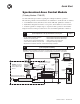
System Configuration and Wiring Chapter 2
Important:
Connect the following to earth ground: a) all
cable shields (except for amplifier output cable)
at
one end only b) LDT flange and machine frame c) IFM T
erminal
Block GND terminal 51 d) I/O chassis
Drive
Output
Valve
Servo or
Proportional
Amplifier
24V Power
Supply
"
15V Power
Supply
for
LDT
s
earth
ground
(+) (–)
(–) (C) (+)
Belden
8761
Belden
8761
Belden
8770
Piston-type Hydraulic Cylinder and
Linear Displacement T
ransducer (LDT)
0V (internal)
+
–
Pwr
Int
Ret
Axis Loop 1 of 4-axis system
IFM Terminal Block
Cat. No. 1492-AIFMQS
Cable 1492-
ACABLExxxQS
Belden
8105
Connect cable shields of servo
amplifier and LDT to SH termi
-
nals on terminal block.
HYDRAULIC
SYNCHR AXES
1746-QS
module
1747-CP3
Cable
PC
Important:
The module’
s
analog outputs require an
external amplifier to drive
the valve.
Quick Start