
User Manual


Chapter 2
Publication
1746-6.19 March 1998
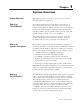
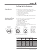
Setting Up the Hardware
This chapter helps you install the hardware with these tasks:
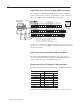
• connecting LDTs to the Interface Module (IFM) terminal block
• minimizing interference from radiated electrical noise
• connecting outputs to output devices
• checking out the wiring and grounding
• setting up the hydraulics
• regarding the Interface Module (IFM) terminal block and cable
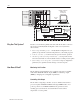
We assume that you will use one of the following types of LDT:
• Temposonics II: RPM TTSRxxxxxxR, or
DPM TTSRxxxxxxDExxx
• Balluff: BTL-2-L2, or BTL-2-M2
• Santest: GYRP, or GYRG
• Gemco Quick-Stick II: 951VP, or 951 RS
We illustrate connections for these types of LDTs. (There are other
suppliers with compatible LDTs.)
10
1
23
4
5
6
7
8
9
Interro-
gate
"15V
dc PS
PS
Common
Frame
GND
Return
(+)
(+)
(–)
(–)
(–)
(+)
Temposonics II,
RPM or DPM
1
2
3
45
6
"15V
dc PS
Balluff
BTL-2-L2
&
-2-M2
Return
(–)
Interro-
gate (+)
1
2
3
4
5
6
+15V
dc PS
Return
(+)
Return
(–)
Interrogate
PS
Common
7
(+)
(–)
NC
Santest
GYRP
&
GYRG
Gemco Quick-Stick II
951VP
w/PWM
Output
B–BLK PS Common
C–RED +15V dc PS
K–GRY + Interrogate
E–BRN –Return*
F–BLU +Return*
A–WHT –Interrogate
G, D, H RS232RXD
J–PUR 2nd PS COM
*951RS has pulse trigger
7 (+)
(–)
The views are looking at the connector on the LDT head.
8
Interro-
gate (–)
Return
(+)
PS
Common
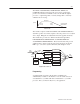
LDT Connections (for fabricating your own LDT cable)
Function Temposonics
II
RPM or DPM
Balluff
BTL-2-L2 & -M2
Santest
GYRP/GYRG
Gemco Quick-
Stick 951VP/RS
(+) Return (note 1) 4 – Pink 2 – Gray pin 5 F – Blue
(–) Return (note 1) 3 – Gray 5 – Green pin 7 E – Brown
(–) Interrogate 10 – Green 3 – Pink pin 6 A – White
(+) Interrogate 9 – Yellow 1 – Yellow pin 4 K – Gray
–15V dc PS 6 – Blue 8 – White n/a n/a
PS Common 1 – White 6 – Blue pin 3 B – Black
+15V dc PS 5 – Red 7 – Brown pin 1 C – Red
(+) and (–) wires of the same function should be a twisted pair within the cable.
(note 1) We use the term “Return” for gate out, pulse trigger, or square wave (Gemco) and
start/stop (Balluff -M2) LDT signals.
Chapter Objectives
Connections to LDTs and
4-axis Terminal Block