
User Manual

1–4
Publication
1746-6.19 March 1998
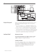
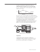
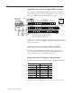
Ladder logic transfers motion commands to the module and axis
status from the module thru the I/O image table. Ladder logic also
copies configuration parameters to the module’s M0 file at power up.
It also copies configuration parameters (that you enter/change with
the Hydraulic Configurator) from the module’s M1 file to processor
files. Thus, you can establish a library of configurations (recipes) in
processor files that you can select and download to the module at
power up or each time you want to change the setup of your axes.
We explain the functions of the ladder logic later in this manual.
Use the module in an SLC-based system for control of hydraulic
applications where two or more axes must reach their final position
at the same time, such as:
• plywood presses
• roll positioning
• palletizers and stackers
• forging machines
• hydraulic tailgate loaders
In addition, the module is designed to support independent axes using
either servo or proportional amplifiers, and retrofit into existing
hydraulic systems requiring a positive voltage irrespective of direction.
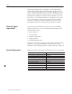
Hardware/software requirements of this SLC processor system include:
Component: Requirement:
SLC Processor SLC 5/03 or later
Comm. Interface Card (alternate COM port) 1784-KTx
Personal Computer 3.9 MByte of disk space
PC Operating System Windows 95
PC/QS Interface Cable 1747-CP3
Synchronized Axes Module 1746-QS
Interface Module (terminal block) 1492-AIFMQS
Interface Module Cable 1492-ACABLExxxQ
Programming Software RSLogix500
LDT (RPM or DPM) Temposonics, Baluff, Santest, Gemco, etc
What Are Typical
Applications?
System Requirements