
User Manual

1–3
Publication
1746-6.19 March 1998
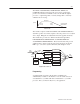
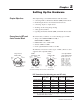
The MODE, ACCELERATION, DECELERATION, SPEED, and
COMMAND
V
ALUE (requested position) are used to generate the
profile. You send these command words to the module through the
processor’s output image table. You may change them “on-the-fly“
while the axis is moving.
Motion
Profile
Speed
Time
Accel
Ramp
Decel
Ramp
Max Speed
Command V
alue
(Final Position)
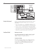
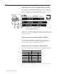
The module compares ACTUAL POSITION with TARGET POSITION to
determine position error. Every update, it uses the position error to adjust
drive output. PID gains are adjustable and can be applied selectively.
The module also provides two different feedforward algorithms;
EXTEND/RETRACT FEEDFORWARD, and EXTEND/RETRACT
ACCELERATION FEEDFORWARD. These feedforward terms provide
additional drive output to help the axis follow the target, freeing the
PID loop to correct for system nonlinearity and changes in load.
Diagram of the Control Loop
Proportional Gain
Integral Gain
Dif
ferential Gain
Feedforward
Accel
Feedforward
Deadband
Eliminator
Accumulator
(Integrator)
Change in Error
(Differentiator)
Change in Position
(Velocity)
Change in V
elocity
(Acceleration)
T
arget
Generator
SLC
Processor
Position
Error
Actual
Position
T
arget
Position
Drive
Output
+
–
ȍ
ȍ
Programming
A sample ladder program for the module is available from
Allen-Bradley’s website on the Internet. You can download it as an
executable file to your PC’s disk drive and transfer it to your SLC
processor. But, you must modify it for your application.