
User Manual

Index
I–2
Publication
1746-6.19 March 1998
L
ladder
logic (see sample programs)
data transfer concepts, C-1
download from Internet, 5-1
processor files, C-1
sample programs, 5-2
words/bits, 5-2
LDT
connections to, 2-1, 2-2
identify type in Hydraulic Configurator
, 4-1
length/resolution of, A-1
types, 2-1
LED indicators, 6-1
M
M0/M1 files, C-3, C-4
I/O configuration in SLC, 5-1
ladder to copy parameters to module, 5-3
N
N files, chapter 5, appendix C
noise, electrical, 2-3
null drive, finding its value, 4-1
O
of
fset, finding its value, 4-2, 4-3
output
connections, of module, 2-3, 2-4
image table, C-2, C-4
polarity
, 2-4
overview
, of module and system, 1-1
P
parameters
adjusting while tuning, 4-7, 4-8
saving, 4-10
transferring, C-2
processor
, configure of
fline, 5-1
profile, motion, 1-3
commands, 4-5
programming, 5-4, 5-7, 5-9
programming (see sample programs)
Q
QS module
communication with PC, 3-2
connections to IFM terminal block, 2-2
control loop, 1-3
how it works, 1-2
inputs, 2-2, B-1
outputs, 2-4, B-1
specifications, A-1
what it is, 1-1
quick start, see publication 1746-10.3
R
retract limit,
set value of, 4-2, 4-3, 4-4
programming, 5-4, 5-7
S
sample program
back/forth motion with state machine, 5-4
copy parameters to module, 5-3
copy parameters to SLC processor, 5-3
hydraulics on/off response, 5-8
jogging an axis, 5-7
synchronized axes, 5-9
saving parameters, 4-10
scale, finding its value, 4-2, 4-3
shielding, of cables, 2-3, 2-5
SLC-500 system
overview
, 1-1
requirements, 1-4
specifications, A-1
status word,
bit map, C-6
transferring from module, C-2
stop axis movement, 4-10
T, U, V
terminal
block (Interface Module), 2-2, 2-6
troubleshooting, 6-1
tuning, axis
adjusting parameters, 4-7 thru 4-9
general procedure, 4-5
null drive procedure, 4-1
scale/offset procedure, 4-2, 4-3
W, X, Y
, Z
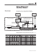
wiring,
2-3, 2-5, B-1