
User Manual

Publication 1746-6.19 March 1998
A
applications,
of module, 1-4
axis,
connections for control loop, 2-3
getting ready to move, 4-5
jogging, sample program, 5-7
stopping axis motion, 4-10
synchronized motion, 5-9
tuning, 4-1
B
benefits, of module, 1-2
bits, 5-2, C-5, C-6
C
cables, 4-3
Interface Module to QS module, 2-6
grounding of, 2-3
PC to module, 2-3, 3-2
system, 1-2, 2-3
calibration, set scale and offset, 4-3, 4-4
commands, to module,
“K” Kill, 4-2
“N” Null Drive, 4-2
“O” Open-loop, 4-2, 4-4
“P” Parameters, 4-3, 4-4
command-mode word, bit map, C-6
command words, 1-3
transferring to module, C-2
used in tuning, 4-7
configure
PC com port, 3-2
I/O for SLC processor
, 5-1
configuration parameters,
see parameters
configuration word, bit map, C-5
connections, to,
Interface Module (terminal block), 2-2
LDT
, 2-1, 2-2
module, 2-3, B-1
module outputs, 2-4
D
data transfer
, C-1
dead band eliminator, find value of, 4-9
diddle box, 4-2
download, from Internet
E
electrical noise, minimize, 2-3, 2-4, 2-5
error,
following, 4-6
Sun-Error
2
, 4-6, 4-8
extend limit,
set value of, 4-2, 4-3, 4-4
programming, 5-4, 5-7
F
fault, module and axis, 6-1
files,
F (floating point), C-1, C-3
N (integer), 5-2, C-2,
M0/M1, C-3, C-4
processor
, 5-2, appendix C
floating point, C–3
following error
, 4-6
fusing, on Interface Module, 2-2
G
grounding, 2-3, 2-4, 2-5, B-2
H
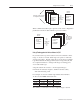
hardware, setting up, 2-1
hydraulics,
setting up, 2-5
programming for power cycles, 5-8
hydraulic configurator
,
communication, PC to module, 3-2
download software to PC, 3-1
setting up, 3-1
what it is, 1-1
I
ID of module, 5-1
input image table, C-1, C-2, C-5
Interface Module (terminal block), 2-2, 2-6
Internet, access to, 3-1, 5-1
J, K
jog
axis, 4-4
sample program, 5-7