
User Manual

Using Processor FilesC–6
Publication
1746-6.19 March 1998
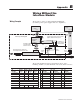
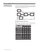
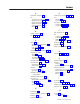
Bit Map of Command Mode Word
Word Bit Description
15
0 =
plots each move of the axis, overwwriting previous plot
1 =
disables axis plot to preserve the last plot
Command Mode
(Co and word )
14-08 reserved
Co and Mode
(Command word 0)
07
0 = disables S Curve
1 = module computes an S-curve target for smoother motion
06
0 = disables Quick Mode
1 =
module ramps up to (max) drive output in open loop,
maintains it, then ramps down in closed loop axis limit
05-04
Synch A/B: Axes with same bit set are synchronized
03-02
Integrator Mode = bit combination
Bit 03 Bit 02 Integrator is Active
0 0 always
01
during DECEL and IN POSITION
10
during IN POSITION
11
never
01-00
Accel/Decel Mode = bit combination
Bit 01 Bit 00
Accel/Decel values define:
00
ramp rate in position units/sec/sec
01
ramp rate in 1000 position units/sec/sec
10
distance to SPEED
11
time to SPEED
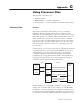
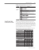
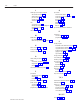
Bit Map of Axis Status Word
Word Bit Description
15
0 =
LDT input OK
1 =
LDT input lost
14
0 =
LDT input OK
1 =
LDT input noisy
For hard/soft stop, see config auto-stop, bit 06
Ax
i
s
Statu
s
(Statu word 4)
13
0 =
LDT input OK
1 =
LDT input overflow
For hard/soft stop, see config auto-stop, bit 05
Ax
i
s
Statu
s
(Status word 4)
12
0 =
output drive power OK
1 =
output drive exceeds D/A range (insufficient drive power)
For hard/soft stop, see config auto-stop, bits 12 and 04
11
0 =
no parameter error detected
1 =
initialization or control parameter is out of bounds
For hard/soft stop, see config auto-stop, bits 1
1 and 03
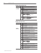
10
0 =
no position overflow detected
1 =
actual position exceeded range of 16-bit number display
09
0 =
integrator windup OK
1 =
integrator value exceeded 20% or 80% (see config bit 00)
For hard/soft stop, see config auto-stop, bits 09 and 01
08
0 =
following error OK
1 = dif
ference between target and actual positions > max error
For hard/soft stop, see config auto-stop, bits 08 and 00
07
0/1 =
toggles to acknowledge valid command or status request
received by the module
06
0 =
module not initialized (module is reset)
1 =
initialized with P command (axis ready for Go command)
05-04
State of target generator = bit combination
Bit 05 Bit 04
T
arget Generator is
0 0 stopped
0 1 accelerating
10
at constant speed
11
decelerating
03
0 = axis in closed loop
1 =
axis in open loop, caused by O command or hard stop
02
0 =
axis movement
1 =
axis is halted, caused by H command, hard or soft stop
01
0 =
axis movement
1 =
axis speed < 500 transducer counts (cleared @ 1000 cts)
00
0 =
axis outside in-position window
1 = dif
ference between actual and command positions is less
then the in-position value