
User Manual

Using Processor FilesC–4
Publication
1746-6.19 March 1998
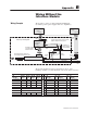
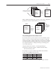
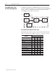
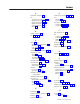
Configuration parameters for M0 and M1 files can be stored in three
locations: on PC disk, in SLC-processor N files, and in module FLASH
memory. The “P” command activates the parameters (moves them
from RAM to control CPU in the module).
Configuration
Parameters
PC
Configuration
Parameters
SLC
Configuration
Parameters
QS
Module
M0/M1 Files
in Module
RAM
Module’s
Control
CPU
P Cmd.
COPY
Disk
N Files
FLASH
Power-up
P Cmd.
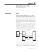
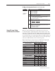
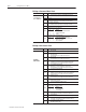
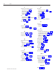
M0 and M1 Memory Map for Ladder Logic
M0 and M1 files both have the same 16-word memory map. They are
addressed in ladder logic as M0e:n or M1e:n (e = rack #, n = word #).
Copy
these
parameters:
T
o/From these file addresses:
Copy
these
parameters:
Axis 1 Axis 2 Axis 3 Axis 4
Configuration
e.0 e.16 e.32 e.48
Scale e.1 e.17 e.33 e.49
Offset e.2 e.18 e.34 e.50
Extend Limit
e.3 e.19 e.35 e.51
Retract Limit
e.4 e.20 e.36 e.52
Proportional Gain
e.5 e.21 e.37 e.53
Integral Gain
e.6 e.22 e.38 e.54
Dif
ferential Gain
e.7 e.23 e.39 e.55
Extend Feedforward
e.8 e.24 e.40 e.56
Retract Feedforward
e.9 e.25 e.41 e.57
Extend Accel Feedforward
e.10 e.26 e.42 e.58
Retract Accel Feedforward
e.11 e.27 e.43 e.59
Dead Band Eliminator
e.12 e.28 e.44 e.60
In Position e.13 e.29 e.45 e.61
Following Error
e.14 e.30 e.46 e.62
Auto Stop
e.15 e.31 e.47 e.63
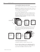
Using M0 and M1 Files
for Initial Configuration