
User Manual

Appendix
B
Publication
1746-6.19 March 1998
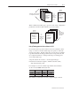
Wiring Without the
Interface Module
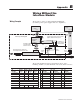
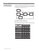
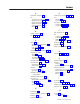
We present a 1-axis loop with a differential LDT input.
(You must provide power supplies and servo amplifiers.)
LDT
and Hydraulic Ram
Drive Output
Valves
Servo
Proportional
Amplifier
24V Power
Supply
"
15V Power
Supply
earth ground
(+) (–)
(–) (C) (+)
Belden
8761
Belden
8761
Belden
8770
Piston-type Hydraulic Cylinder and
Linear Displacement T
ransducer (LDT)
0V (internal)
Pwr
Int
Ret
Axis Loop 1 of 4-axis system
Belden
8105
Connect cable shields to earth ground.
Connect signal commons and PS commons
together
,
isolated
from earth ground.
11
3 2 1 8
1713
+–
+
–
Signal
Common
Pin Numbers of
Signal Cable from
1746-QS Module
Fused
Connector
Grounding exception:
Connect this shield
to internal common.
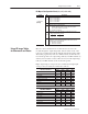
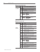
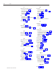
We present the DB-26 connector pin functions in two ways:
LDT/loop number (1-4) and numerical order (1-26) in the connector:
by LDT/Loop in Numerical Order
I/O
Function
Pins for
Loop 1
Pins for
Loop 2
Pins for
Loop 3
Pins for
Loop 4
Pin
#
I/O
Function
Pin
#
I/O
Function
Pin
#
I/O
Function
(+) Interrogate 1 10 4 22 1 (+) Interrogate 1 10 (+) Interrogate 2 19 (–) Interrogate 2
(–) Interrogate 11 19 5 14 2 (+) Return 1 11 (–) Interrogate 1 20 (+) Return 2
(+) Return 2 20 15 23 3 (–) Return 1 12 (–) Return 2 21 LDT Common
(–) Return 3 12 6 24 4 (+) Interrogate 3 13 LDT Common 22 (+) Interrogate 4
LDT Common 13, 21 5 (–) Interrogate 3 14 (–) Interrogate 4 23 (+) Return 4
n/c 7, 16 6 (–) Return 3 15 (+) Return 3 24 (–) Return 4
Drive Common 8, 26 7 n/c 16 n/c 25 Drive Output 2
Drive Output 17 25 9 18 8 Drive Common 17 Drive Output 1 26 Drive Common
9 Drive Output 3 18 Drive Output 4
Wiring Example