
User Manual

toc–i
Publication
1746-6.19 – March 1998
System Overview Chapter 1
Chapter Objectives
1–1
. . . . . . . . . . . . . . . . . . . . . . . . . . . . . . . . . . .
What
Is the 1746-QS Module?
1–1
. . . . . . . . . . . . . . . . . . . . . . . . . . .
What
Is the Hydraulic Configurator
1–1
. . . . . . . . . . . . . . . . . . . . . . . .
What Is an SLC-500 System?
1–1
. . . . . . . . . . . . . . . . . . . . . . . . . . . .
Why Use This System?
1–2
. . . . . . . . . . . . . . . . . . . . . . . . . . . . . . . .
How Does It Work?
1–2
. . . . . . . . . . . . . . . . . . . . . . . . . . . . . . . . . . .
Controlling Axis Output
1–2
. . . . . . . . . . . . . . . . . . . . . . . . . . . . . . .
Programming
1–3
. . . . . . . . . . . . . . . . . . . . . . . . . . . . . . . . . . . . .
What
Are Typical Applications?
1–4
. . . . . . . . . . . . . . . . . . . . . . . . . . .
System Requirements
1–4
. . . . . . . . . . . . . . . . . . . . . . . . . . . . . . . . .
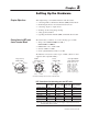
Setting Up the Hardware Chapter 2
Chapter Objectives
2–1
. . . . . . . . . . . . . . . . . . . . . . . . . . . . . . . . . . .
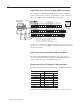
Connections
to LDT
s and 4-axis Terminal Block
2–1
. . . . . . . . . . . . . . .
LDT
Connections (for fabricating your own LDT cable)
2–1
. . . . . . . .
Typical
Connections to the Interface Module (IFM) T
erminal Block
2–2
T
ypical Fusing of the Interface Module (IFM) T
erminal Block
2–2
. . . .
Example
Connections for T
emposonics II Dif
ferential Inputs
2–2
. . . .
Wiring Example
2–3
. . . . . . . . . . . . . . . . . . . . . . . . . . . . . . . . . . . .
Minimizing
Interference from Radiated Electrical Noise
2–3
. . . . . . . . . .
Connecting Outputs to Output Devices
2–4
. . . . . . . . . . . . . . . . . . . . .
Output
Polarity
2–4
. . . . . . . . . . . . . . . . . . . . . . . . . . . . . . . . . . . .
Checking
Out the Wiring and Grounding
2–5
. . . . . . . . . . . . . . . . . . . .
Setting Up the Hydraulics
2–5
. . . . . . . . . . . . . . . . . . . . . . . . . . . . . . .
Regarding
the Interface Module T
erminal Block and Cable
2–6
. . . . . . .
Setting Up Your PC
for the Hydraulic Configurator
Chapter 3
Chapter Objectives
3–1
. . . . . . . . . . . . . . . . . . . . . . . . . . . . . . . . . . .
Obtaining
the Hydraulic Configurator from the Internet
3–1
. . . . . . . . . .
To Access Our Website:
3–1
. . . . . . . . . . . . . . . . . . . . . . . . . . . . . .
To
Load the Hydraulic Configurator:
3–1
. . . . . . . . . . . . . . . . . . . . . .
Setting
Up Communication Between PC and Module
3–2
. . . . . . . . . . .
Tuning an Axis with
the Hydraulic Configurator
Chapter 4
Chapter Objectives
4–1
. . . . . . . . . . . . . . . . . . . . . . . . . . . . . . . . . . .
Before Y
ou Begin
4–1
. . . . . . . . . . . . . . . . . . . . . . . . . . . . . . . . . . . . .
Finding
the V
alue of the Null Drive
4–1
. . . . . . . . . . . . . . . . . . . . . . . . .
Moving
the Axis to Set Scale, Of
fset, Extend, and Retract Limits
4–2
. . .
Procedure
to Set Scale and Of
fset with Drive Output Disconnected
4–2
Alternate Open-loop Procedure to Set Scale and Of
fset
4–3
. . . . . . .
Getting
Ready to Tune the Axes
4–5
. . . . . . . . . . . . . . . . . . . . . . . . . .
Tuning Each Axis
4–5
. . . . . . . . . . . . . . . . . . . . . . . . . . . . . . . . . . . . .
General
Procedure for T
uning an Axis
4–5
. . . . . . . . . . . . . . . . . . . .