
User Manual

4–6
Publication
1746-6.19 March 1998
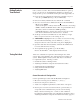
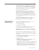
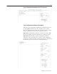
2. The Following Error will probably vary as indicated by diverging plots
of target and actual speeds during acceleration or deceleration.
Target Speed
(pink)
Actual Speed
(dark blue)
Following Error
3. To achieve a nearly constant steady-state Following Error, increase
the
PROPORTIONAL GAIN until the plots of target and actual speeds
become parallel during acceleration or deceleration.
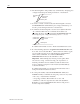
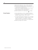
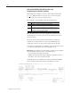
4. To minimize the Following Error, use the auto Adjust Feedforward
“F
” command. With each “F” command, the module boosts
(prescales) the drive output by increasing the
FEEDFORWARD term.
This brings the plots of target and actual positions to coincide.
Target Position
(powder blue)
Following Error
Actual Position
(red)
For additional information, refer to Feedforward Parameters, below.
5. For critical tuning, adjust the
ACCELERATION FEEDFORWARD term.
To do this, observe the Sum-Error
2
value found in the window on the
plot screen. Repeat axis moves with adjustments until Sum-Error
2
value reaches a minimum. Too much ACCELERATION
FEEDFORWARD will increase the Sum-Error
2
value.
Important: Critical tuning may increase pressure spikes. If the
axis load is too large, consider lowering your expectations of
machine performance and use smaller accel/decel values in the
motion command. Using the S-curve feature (Command Mode)
is another alternative.
For additional information on Acceleration Feedforward, refer to
Using Acceleration Feedforward, below.
6. For end-point stability, adjust the
PROPORTIONAL GAIN (and
INTEGRAL GAIN) to minimize the end-point position error by either
of two ways. Adjust P and/or I until the:
– end position oscillates. Then back down to 75% of P.
– Sum-Error
2
value no longer decreases with each adjustment.
Remember to enter an
IN POSITION value in the Config word to
monitor end-position stability.