
Instructions

SLC 500 Thermocouple/mV Analog Input Module 5
Publication 1746-IN015C-EN-P - July 2001
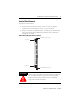
1746-NT8 Features
Installing And Wiring Your Module
Read this section to install and wire your module. This section covers:
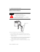
• avoiding electrostatic damage
• determining power requirements
• installing the module
• wiring signal cables to the module’s terminal block
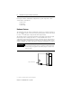
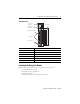
Hardware Function
Channel Status LED Indicators Display operating and fault status of channels 0 through 7
Module Status LED Displays operating and fault status of the module
Side Label (Nameplate) Provides module information
Removable Terminal Block Provides electrical connection to input devices
Door Label Permits easy terminal identification
Self Locking Tabs Secure module in chassis slot
MODULE
0
1
4
5
2
1
2
3
CHANNEL
STATUS
THERMOCOUPLE/mV
INPUT
CJC A+
CJC A-
CHL 0+
CHL 0-
SHIELD
CHL 1+
CHL 1-
CHL 2+
CHL 2-
SHIELD
CHL 3+
CHL 3-
CHL 4+
CHL 4-
SHIELD
CHL 5+
CHL 5-
CHL 6+
CHL 6-
SHIELD
CHL 7+
CHL 7-
CJC B+
CJC B-
1746-NT8
Door Label
Channel Status
LEDs (Green)
Module Status
LED (Green)
Removable Terminal Block
CJC Sensors
Cable Tie Slots