
Instructions

SLC 500 Thermocouple/mV Analog Input Module 15
Publication 1746-IN015C-EN-P - July 2001
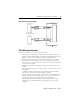
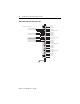
5. Connect the drain wires to the shield inputs of the terminal block if
appropriate for thermocouple used. See “Wiring Guidelines” on page 10 for
more information.
• Channel 0 and 1 drain wires to pin 5
• Channel 2 and 3 drain wires to pin 10
• Channel 4 and 5 drain wires to pin 15
• Channel 6 and 7 drain wires to pin 20
6. Connect the signal wires of each channel to the terminal block.
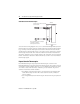
7. Connect TB1 chassis ground connector to the nearest chassis mounting bolt
with 14 gauge wire. (On the face of the module, TB1 is near the lower part
of the terminal block on the primary side of the PCB.)
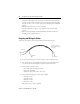
8. At the sensor-end of cables from thermocouple/mV devices:
• remove the drain wire and foil shield
• apply shrink wrap as an option
• connect to thermocouple/mV devices keeping the leads short
IMPORTANT
Only after verifying that your connections are correct for
each channel, trim the lengths to keep them short. Avoid
cutting leads too short.
IMPORTANT
If noise persists, try grounding the opposite end of the cable
instead. (Ground one end only.)
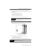
TB1
Connect ground wire to TB1 before installing module.