
User Manual Owner's manual


Publication 1746-UM022B-EN-P - January 2005
Troubleshooting Your Module 6-5
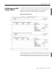
Channel Error (Bit 15)
The module sets this fault bit when it detects any of the following
configuration errors:
• configuration bits 1 through 4: invalid input type = 1010, 1011,
1100, 1101, or 1110.
• configuration bits 12 through 14: invalid non-zero bit setting.
• invalid data acquisition of an input channel.
• the filter frequency selected for the valid channel currently fails
auto-calibration range checks.
Module Status LED (Green)
The module-status LED indicates when the module detects a
non-recoverable fault at power up or during operation. For this type
of fault, the module:
• no longer communicates with the SLC processor
• disables all channels
• clears all data and status words
A module failure is non-recoverable and requires the assistance of
your local Allen-Bradley distributor.
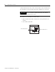
Interpreting I/O Error Codes
I/O error codes appear in word S:6 of the SLC processor status file.
The first two digits of the error code identify the slot (in hexadecimal)
with the error. The last two digits identify the I/O error code (in
hexadecimal).
The error codes that apply to your module include (in hexadecimal):
• 50 through 5E
• 71 (watchdog error)
• 90 through 94
For a description of the error codes, refer to the SLC 500 Instruction
Set Reference Manual, publication 1746-RM001.