
User Manual Owner's manual


Publication 1746-UM022B-EN-P - January 2005
5-4 Programming Examples
S:1
15
COP
Copy File
Source #N10:0
Dest #O:1.0
Length 8
COP
#NT8_CONFIGURATION
U
B3:6
4
CHECKING_CJC
B3:6
4
CHECKING_CJC
MOV
Move
Source I:1.0
3744<
Dest N10:20
3744<
MOV
CH0_TEMP
COP
Copy File
Source #I:1.1
Dest #N10:21
Length 7
COP
T11:0
DN
CJC_CYCLE_TMR/DN
EN
DN
TON
Timer On Delay
Timer T11:0
Time Base 1.0
Preset 60<
Accum 20<
TON
CJC_CYCLE_TMR
T11:0
DN
CJC_CYCLE_TMR/DN
MOV
Move
Source N10:8
-32737<
Dest O:1.0
-32767<
MOV
NT8_CONFIGURATION
L
B3:6
4
CHECKING_CJC
F irst Pass
0000
0003
0004
0002
0001
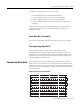
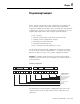
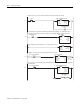
During the first pass, send the channel configuration data to the thermocouple module.
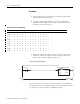
If not Checking CJC, copy Channel 0 temperature data into data location for use. Temperature control
logic should use N10:20 rather than the TC image (I:1.0) to eliminate problems during CJC checking.
Copy temperature data from Channels 1 to 7 to data registers for use.
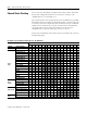
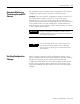
Repeating 60 seconds timer (T 11:0) which starts the CJC check cycle.
Every 60 seconds, start CJC check cycle by changing Channel 0 configuration word and latching Checking
CJC bit (B3/100).