
User Manual Owner's manual


1 Publication 1746-UM022B-EN-P - January 2005
Chapter
5
Programming Examples
Earlier chapters explained how the configuration word defines the
way a channel operates. This chapter shows the programming
required to configure the module. It also provides you with segments
of ladder logic specific to unique situations that might apply to your
programming requirements. The example segments include:
• basic example
• automatic monitoring thermocouples and CJC sensors
• verifying channel configuration changes
• interfacing to the PID instruction
• monitoring channel status bits
• PLC 5 example with NT8 in Remote I/O rack
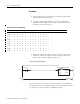
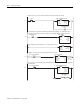
To enter data into the channel configuration word (O:e.0 through
O:e.7) when the channel is disabled (bit 0 = 0), follow these steps.
Refer to the table on page 4-4 for specific configuration details.
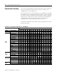
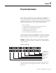
Example - Configure eight channels of a thermocouple module
residing in slot 3 of 1746 chassis. Configure each channel with the
same parameters.
Channel Configuration
The following procedure transfers configuration data and sets the
channel enable bits of all eight channels with a single File Copy
instruction.
1 1
0
00 1 00 01 0001
15 14 13 12 11 10
9
87 65 4321
000
Configure Channel for:
Channel E Enable Bit
Type K Thermocouple Input
Engineering Units X 10
Zero if Open Circuit
Fahrenheit
10 Hz Filter Frequency
Not Used
Data Word