SLC 500 Thermocouple/mV Analog Input Module 1746-NT8 User Manual
Important User Information Solid state equipment has operational characteristics differing from those of electromechanical equipment. Safety Guidelines for the Application, Installation and Maintenance of Solid State Controls (Publication SGI-1.1 available from your local Rockwell Automation sales office or online at http://www.ab.com/manuals/gi) describes some important differences between solid state equipment and hard-wired electromechanical devices.
Table of Contents Preface Who Should Use This Manual . . . . . . . . . What This Manual Covers . . . . . . . . . . . . Related Documentation . . . . . . . . . . . . . Common Techniques Used in this Manual . . . . . . . . . . . . . . . . . . . . . . . . . . . . . . . . . . . . . . . . . . . . . . . . . . . . P-1 P-1 P-2 P-2 . . . . . . . . . . . . . . . . . . . . . . . . . . . . . . . . . . . . . . . . . . . . . . . . . . . . . . . . . . . . . . . . . . . . . . . . . . . . . . . . . .
Table of Contents ii Chapter 4 Channel Configuration, Data, and Status Channel Configuration . . . . . . . . . . . . . . . . . . . . . . Channel Configuration Procedure . . . . . . . . . . . . . . Select Channel Enable (Bit 0) . . . . . . . . . . . . . . . Select Input Types (Bits 1 through 4) . . . . . . . . . Select Data Format (Bits 5 and 6) . . . . . . . . . . . . Using Scaled-for-PID and Proportional Counts . . Effective Resolutions . . . . . . . . . . . . . . . . . . . . . Scaling Examples . . . .
Table of Contents iii Out-of-Range Detection (Bit 13 for Under Range, Bit 14 for Over Range) . . . . . . . . . . . . . . . . . . . . . . . . . . . . . . . . 6-4 Channel Error (Bit 15) . . . . . . . . . . . . . . . . . . . . . . . . . 6-5 Module Status LED (Green) . . . . . . . . . . . . . . . . . . . . . 6-5 Interpreting I/O Error Codes . . . . . . . . . . . . . . . . . . . . . . . 6-5 Chapter 7 Maintaining Your Module And Safety Considerations Preventive Maintenance. . . . . . . . . . . . . . . . . . .
Table of Contents iv Publication 1746-UM022B-EN-P - January 2005
Summary of Changes The information below summarizes the changes to this manual since the last printing. Updates to the manual include using RSLogix 500 instead of APS software. To help you find new and updated information in this release of the manual, we have included change bars as shown to the right of this paragraph. The table below lists the sections that document new features and additional or updated information on existing features.
Summary of Changes 2 Publication 1746-UM022B-EN-P - January 2005
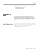
Preface Read this preface to familiarize yourself with this user manual. This preface covers: • • • • Who Should Use This Manual who should use this manual what this manual provides related documents common techniques used in this manual Use this manual if you design, install, program, or maintain a control system that uses SLC 500 controllers. You should have a basic understanding of SLC 500 products.
Preface 2 Related Documentation The following table lists several Rockwell Automation documents that may help you as you use these products. Publication Number Title 1746-SG001 SLC 500™ Systems Selection Guide SGI-1.1 Safety Guidlines for the Application, Installation and Maintenance of Solid State Controllers 1770-4.1 Industrial Automation Wiringing and Grounding Guidelines 1747-UM011 SLC 500 Modular Modular Hardware Style User Manual 1747-6.
Chapter 1 Module Overview This chapter describes the thermocouple/mV input module and explains how the SLC 500 processor reads thermocouple or millivolt analog input data from the module. Read this chapter to familiarize yourself further with your thermocouple/mV analog input module.
1-2 Module Overview Type °C Temperature Range °F Temperature Range S 0°C to +1768°C +32°F to +3214°F N 0°C to +1300°C +32°F to +2372°F CJC Sensor -25°C to +105°C -13°F to +221 °F Millivolt Input Ranges(1) -50 to +50 mV -100 to +100 mV Each input channel is individually configured for a specific input device, and provides open-circuit, over-range, and under-range detection and indication.
Module Overview Side Label Channel Status LEDs (green) INPUT 0 1 2 1 4 5 2 3 Door Label THERMOCOUPLE/mV ) SA INPUT SIGNAL RANGES THERMOCOUPLE TYPES: J, K, T, E, R, S, B, N VOL TAGE: ±50mVDC to +50mVDC ±100mVDC to +100mVDC FAC 1M MADE IN USA Cable Tie Slots OPERA TING UL LISTED IND. CONT . EQ. ) TEMPERA TURE CODE T3C FOR HAZ. LOC. A196 CLASS I, GROUPS A, B, C AND D, DIV.
1-4 Module Overview Each module channel can receive input signals from a thermocouple or a mV analog input device. You configure each channel to accept either one. When configured for thermocouple input types, the module converts analog input voltages into cold-junction compensated and linearized, digital temperature readings. The module uses National Institute of Standards and Technology (NIST) ITS-90 for thermocouple linearization.
Module Overview 1-5 Module Operation The module’s input circuitry consists of eight differential analog inputs, multiplexed into an A/D convertor. The A/D convertor reads the analog input signals and converts them to a digital value. The input circuitry also continuously samples the CJC sensors and compensates for temperature changes at the cold junction (terminal block). Module Addressing The module requires eight words each in the SLC processor’s input and output image tables.
1-6 Module Overview Block Diagram Terminal Block ungrounded thermocouple Module Circuitry C JC A Sensor + - + Shield + + - Wit hin 12.
Module Overview 1-7 Linear Millivolt Device Compatibility(1) A large number of millivolt devices may be used with the 1746-NT8 module. For this reason we do not specify compatibility with any particular device. However, millivolt applications often use strain gage bridges. A resistive voltage divider using fixed resistors is recommended for this application. The circuit diagram below shows how this connection is made.
1-8 Module Overview Publication 1746-UM022B-EN-P - January 2005
Chapter 2 Installing And Wiring Your Module Read this chapter to install and wire your module. This chapter covers: • • • • Electrostatic Damage avoiding electrostatic damage determining power requirements installing the module wiring signal cables to the module’s terminal block Electrostatic discharge can damage semiconductor devices inside this module if you touch backplane connector pins.
2-2 Installing And Wiring Your Module Power Requirements The module receives its power through the SLC 500 chassis backplane from the fixed or modular +5 V dc/+24 V dc chassis power supply. The maximum current drawn by the module is shown in the table below. Maximum Current Drawn by the Module 5Vdc Amps 24Vdc Amps 0.120 0.
Installing And Wiring Your Module 2-3 Fixed I/O Chassis - I/O Module Compatibility The following chart depicts the range of current combinations supported by the fixed I/O expansion chassis. To use it, find the backplane current draw and operating voltage for both modules being used in the chassis. These specifications are found in the table alongside the chart. Next, plot each of the currents on the chart below. If the point of intersection falls within the operating region, the combination is valid.
2-4 Installing And Wiring Your Module When using the BAS or KE module to supply power to a 1747-AIC Link Coupler, the link coupler draws its power through the module. The higher current drawn by the AIC at 24V dc is shown in the table as BASn (BAS networked) and KEn (KE networked). Be sure to use these current draw values if the application uses the BAS or KE module in this way.
Installing And Wiring Your Module 2-5 Module Installation and Removal ATTENTION Possible Equipment Operation Before installing or removing your module, always disconnect power from the SLC 500 system and from any other source to the module (in other words, do not ’hot swap’ your module), and disconnect any devices wired to the module. Failure to observe this precaution can cause unintended equipment operation and damage.
2-6 Installing And Wiring Your Module 4. Cover all unused slots with the Card Slot Filler, Allen-Bradley part number 1746-N2. Terminal Block Removal To remove the terminal block: 1. Loosen the two terminal block release screws. To avoid cracking the terminal block, alternate between screws as you remove them. 2. Using a screwdriver or needle-nose pliers, carefully pry the terminal block loose. When removing or installing the terminal block be careful not to damage the CJC sensors.
Installing And Wiring Your Module 2-7 Terminal block diagram with CJC sensors Terminal Block Release Screws CJC Sensors R ecommended Torque: wiring screws: 0.25 Nm (2.2 in-lb) release screws: 0.25 Nm (2.2 in-lb) CJC Sensors Terminal Block Release Screws ATTENTION Possible Equipment Operation Before wiring your module, always disconnect power from the SLC 500 system and from any other source to the module. Failure to observe this precaution can cause unintended equipment operation and damage.
2-8 Installing And Wiring Your Module Wiring Your Module Follow these guidelines to wire your input signal cables: • Power, input, and output (I/O) wiring must be in accordance with Class 1, Division 2 wiring methods [Article 501-4(b) of the National Electrical Code, NFPA 70] and in accordance with the authority having jurisdiction. • Route thermocouple and millivolt signal wires as far as possible from sources of electrical noise, such as motors, transformers, contactors, and ac devices.
Installing And Wiring Your Module 2-9 Preparing and Wiring the Cables To prepare and connect cable leads and drain wires, follow these steps: Cable (Remove foil shield and drain wire from sensor end of the cable.) Signal Wires Drain Wire Signal Wires 1. At each end of the cable, strip some casing to expose individual wires. 2. Trim signal wires to 5-inch lengths beyond the cable casing. Strip about 3/16 inch (4.76 mm) of insulation to expose the ends of the wires. 3.
2-10 Installing And Wiring Your Module 6. Connect the signal wires of each channel to the terminal block. IMPORTANT Only after verifying that your connections are correct for each channel, trim the lengths to keep them short. Avoid cutting leads too short. 7. Connect TB1 chassis ground connector to the nearest chassis mounting bolt with 14 gauge wire. (Looking at the face of the module, TB1 is near the lower part of the terminal block on the primary side of the PCB.
Installing And Wiring Your Module 2-11 Terminal Block Diagram with Input Cable CJC A+ CJC ACh annel 0+ Thermocouple or mV Ca ble Ch annel 0Shield for CH 0 and CH 1 Ch annel 1+ Ch annel 1Ch annel 2+ Ch annel 2Shield for CH 2 and CH 3 Ch annel 3+ Ch annel 3Ch annel 4+ Ch annel 4Shield for CH 4 and CH 5 Ch annel 5+ Ch annel 5Ch annel 6+ Ch annel 6Shield for CH 6 and CH 7 Ch annel 7+ Ch annel 7CJC B + CJC B R ecommended Torque: TB 1 0.3 to 0.5 Nm (2.5 to 4.
2-12 Installing And Wiring Your Module Publication 1746-UM022B-EN-P - January 2005
Chapter 3 Considerations Before Using Your Module This chapter explains how the module and the SLC processor communicate through the processor’s I/O image tables. It also describes the module’s input filter characteristics. Topics discussed include: • • • • • Module ID Code module ID code module addressing channel filter frequency selection channel turn-on, turn-off, and reconfiguration times response to slot disabling The module ID code is unique number assigned to each 1746 I/O module.
3-2 Considerations Before Using Your Module Module Addressing The following memory map shows you how the SLC processor’s output and input tables are defined for the module. Image Table Bit 15 Thermocouple Module Image Table SLC 5/0X Data Files Slot e Output Scan Output Image 8 Words Output Image Slot e Bit 0 Channel 0 Configuration Word Word 0 Address O:e .0 Channel 1 Configuration Word Channel 2 Configuration Word Word 1 O:e .1 Word 2 O:e .2 Channel 3 Configuration Word Word 3 O:e .
Considerations Before Using Your Module 3-3 Chapter 4 provides detailed bit information about the data content of the configuration word. Input Image - Data Words and Status Words Eight words of the SLC processor’s input image table are reserved for the module. Input image words are multiplexed since each channel has one data word and one status word. The corresponding configuration word selects whether the channel status or channel data is in the input image word.
3-4 Considerations Before Using Your Module The following table shows the available filter frequencies, cut-off frequency, step response, and a DC effective resolution for each filter frequency. Cut-off frequency, Step Response Time, and Effective Resolution (Based on Filter Frequency) Filter Frequency Cut-Off Frequency Step Response ADC Effective Resolution 10 Hz 2.62 Hz 400 ms 20.5 50 Hz 13.1 Hz 80 ms 19.0 60 Hz 15.72 Hz 66.7 ms 19.0 250 Hz 65.5 Hz 16 ms 15.
Considerations Before Using Your Module 3-5 Signal Attenuation with 10 Hz Input Filter -3 dB 0 -20 -40 -60 -80 Amplitude (in dB) -100 -120 -140 -160 -180 -200 0 10 20 2.62 Hz 30 40 50 60 Hz 250 300 Hz Signal Frequency Signal Attenuation with 50 Hz Input Filter -3 dB 0 -20 -40 -60 -80 Amplitude (in dB) -100 -120 -140 -160 -180 -200 0 13.
3-6 Considerations Before Using Your Module Signal Attenuation with 60 Hz Input Filter 0 -3 dB -20 -40 -60 -80 Amplitude (in dB) -100 -120 -140 -160 -180 -200 0 60 120 15.7 Hz 180 240 300 360 Hz 1250 1500 Hz Signal Frequency Signal Attenuation with 250 Hz Input Filter -3 dB 0 -20 -40 -60 -80 Amplitude (in dB) -100 -120 -140 -160 -180 -200 0 250 65.5 Hz 500 750 1000 Signal Frequency Channel Step Response The channel filter frequency determines the channel’s step response.
Considerations Before Using Your Module Update Time 3-7 The thermocouple module update time is defined as the time required for the module to sample and convert the input signals of all enabled input channels and make the resulting data values available to the SLC processor. It can be calculated by adding the sum of all enabled sample times, plus a CJC update time.
3-8 Considerations Before Using Your Module Update Time Calculation Example The following example shows how to calculate the module update time for the given configuration: Channel Channel Channel Channel 0 1 2 3 configured for 250 Hz filter frequency, enabled configured for 250 Hz filter frequency, enabled configured for 50 Hz filter frequency, enabled through 7 disabled Using the values from the table on page 3-7, add the sum of all enabled channel sample times, plus one CJC update time.
Considerations Before Using Your Module 3-9 CJC sensors are acquired at 60 Hz to maximize the trade-off between resolution and update rate. For example, if some channels are acquired at 250 Hz and some are acquired at 50 Hz, then the total auto-calibration time would be: Frequency Auto-Calibration 250 Hz 325 ms 60 Hz 525 ms 50 Hz 585 ms 1.435 s Total During auto-calibration, input values are not updated.
3-10 Considerations Before Using Your Module Publication 1746-UM022B-EN-P - January 2005
Chapter 4 Channel Configuration, Data, and Status Read this chapter to: • configure each input channel • check each input channel’s configuration and status Channel Configuration Channel configuration words appear in the SLC processor’s output image table as shown below. Words 0 to 7 correspond to module channels 0 to 7. After module installation, configure each channel to establish the way the channel operates (e.g., thermocouple type, temperature units, etc.).
4-2 Channel Configuration, Data, and Status The configuration word default settings are all zero.
Channel Configuration, Data, and Status 4-3 5. If the channel is configured for thermocouple inputs, determine if the channel data word should read in degrees Fahrenheit or degrees Celsius and enter a one or a zero in bit 9 of the configuration word. If the channel is configured for a mV analog sensor, enter a zero in bit 9. 6. Determine the desired input filter frequency for the channel and enter the two-digit binary code in bits 10 and 11 of the channel configuration word.
4-4 Channel Configuration, Data, and Status A detailed explanation appears in the following table: Channel Configuration Word (0:e.0 through 0:e.
Channel Configuration, Data, and Status 4-5 Select Channel Enable (Bit 0) Use the channel enable bit to enable a channel. The thermocouple module only scans enabled channels. To optimize module operation and minimize throughput times, unused channels should be disabled by setting the channel enable bit to zero (default value). When set (1) the channel enable bit is used by the module to read the configuration word information selected.
4-6 Channel Configuration, Data, and Status The proportional counts are scaled to fit the defined temperature or voltage range. The input signal range is proportional to your selected input and scaled into a -32,768 to 32,767 range. Using Scaled-for-PID and Proportional Counts The thermocouple module provides eight options for displaying input channel data. These are 0.1°F, 0.1°C, 1°F, 1°C, 0.01 mV, 0.1 mV, Scaled-for-PID, and Proportional Counts.
Channel Configuration, Data, and Status 4-7 Scaling Examples Scaled-for-PID to Engineering Units Equation: Engineering Units Equivalent = SLOW + [(SHIGH-SLOW) x (Scaled-for-PID value displayed/16384)] Data: Assume type J input type, scaled-for-PID display type, channel data = 3421. Want to calculate °C equivalent. From Channel Data Word Format table, SLOW = -210°C and SHIGH = 760°C. Solution: Engineering Units Equivalent = -210°C + [(760°C-(-210°C)) x (3421/16384)] = -7.46°C.
4-8 Channel Configuration, Data, and Status 1746-NT8 Thermocouple Module - Channel Data Word Format Data Format Input Type Engineering Units x10 Engineering Units x1 °Celsius °Fahrenheit °Celsius °Fahrenheit J -210 to +760 -346 to +1400 -2100 to +7600 -3460 to +14000 0 to +16383 -32768 to +32767 K -270 to +1370 -454 to +2498 -2700 to +13700 -4540 to +24980 0 to +16383 -32768 to +32767 T -270 to +400 -454 to +752 -2700 to +4000 -4540 to +7520 0 to +16383 -32768 to +32767 E -270
Channel Configuration, Data, and Status IMPORTANT 4-9 Data resolution is not equivalent to data accuracy. Input accuracy of ±50 µV may span multiple steps for PID and Proportional Counts data types. As an example, a Type B thermocouple temperature range of 0 to 1820°C provides a voltage input range of 0 to 13.82mV to the 1746-NT8. This is a very small input range and, when it is scaled to PID or proportional counts ranges, a small input change results in many counts being changed.
4-10 Channel Configuration, Data, and Status For example, if channel one is configured as a thermocouple type when the CJC breaks in an open-circuit condition, if open-circuit detection is disabled, the data word remains unchanged. If the circuit selection is set at minimum, the data word is set to the low scale value for the range and format. IMPORTANT Enabling the open-circuit function adds approximately 45 ms to the channel update time. Disabling the open circuit detection removes the time adder.
Channel Configuration, Data, and Status 4-11 Guidelines for filter frequency are listed below. • • • • 250 Hz setting provides minimal noise filtering. 60 Hz setting provides 60 Hz AC line noise filtering. 50 Hz setting provides 50 Hz AC line noise filtering. 10 Hz setting provides both 50 Hz and 60 Hz AC line noise filtering. When a CJC input type is selected, filter frequency is ignored. To maximize the speed versus resolution trade-off, CJC inputs are sampled at 60 Hz.
4-12 Channel Configuration, Data, and Status Channel Status Checking You can use the information provided in the status word to determine if the input configuration data for any channel is valid per your configuration in O:e.0 through O:e.7. The channel status can be analyzed bit by bit.
Channel Configuration, Data, and Status 4-13 Channel 0 to 7 Status Word (I:e.0 through I:e.
4-14 Channel Configuration, Data, and Status Data Format Type Status (Bits 5 and 6) The data format bit field indicates the data format you have defined for the channel. This field reflects the data type selected in bits 5 and 6 of the channel configuration word. Open-Circuit Type Status (Bits 7 and 8) The open-circuit bit field indicates how you have defined the open-circuit bits configuration word, and therefore, the response of the thermocouple module to an open-circuit condition.
Channel Configuration, Data, and Status 4-15 Over-Range Error (Bit 14) This bit is set (1) whenever a configured channel detects an over range condition for the channel data. An over-range condition exists when the input value is equal to or above the specified upper limit of the particular sensor connected to that channel. Channel Error (Bit 15) This bit is set (1) whenever a configured channel detects an error in the configuration word, or an error has occurred while acquiring the A/D data value.
4-16 Channel Configuration, Data, and Status Publication 1746-UM022B-EN-P - January 2005
Chapter 5 Programming Examples Earlier chapters explained how the configuration word defines the way a channel operates. This chapter shows the programming required to configure the module. It also provides you with segments of ladder logic specific to unique situations that might apply to your programming requirements.
5-2 Programming Examples Procedure 1. Create integer file N10. Integer file N10 should contain eight elements (N10:0 through N10:7). 2. Using the programming software, enter the configuration parameters for all eight thermocouple channels into data file locations N10:0 through N10:7.
Programming Examples Automatic Monitoring Thermocouples and CJC Sensors The following example explains how to change data in the channel configuration word when the channel is currently enabled. Example - Execute a dynamic configuration change to channel 0 of the thermocouple module located in slot 1 of a 1746 chassis. Periodically (e.g., every 60 seconds) change from monitoring an external type K thermocouple to monitoring the CJC sensors mounted on the terminal block.
5-4 Programming Examples During the first pass, send the channel configuration data to the thermocouple module. F irst Pa ss S:1 0000 15 #NT8_CONFIGURATION COP Copy File Source #N10:0 Dest #O:1.0 Length 8 CHECKING_CJC B3:6 U 4 If not Checking CJC, copy Channel 0 temperature data into data location for use. Temperature control logic should use N10:20 rather than the TC image (I:1.0) to eliminate problems during CJC checking.
Programming Examples 5-5 Wait 7 seconds for Channel 0 to accept CJC configuration and provide a data value (time depends on module configuration). 0005 CHECKING_CJC B3:6 CJC_CFG_TMR TON Timer On Delay Timer T11:1 Time Base 1.0 Preset 7< Accum 0< 4 EN DN Copy CJC Temperature (I:1.0) into CJC register (N10:12) 0006 CJC_CFG_TMR/DN T11:1 DN B3:0 OSR 4 CJC_TEMP MOV Move Source Dest I:1.
5-6 Programming Examples Data Table for Configuration Changes address N10:0 N10:1 N10:2 N10:3 N10:4 N10:5 N10:6 N10:7 15 0000 0000 0000 0000 0000 0000 0000 0000 data 0010 0010 0010 0010 0010 0010 0010 0010 0010 0010 0010 0010 0010 0010 0010 0010 0 0011 0011 0011 0011 0011 0011 0011 0011 address N10:8 15 data 0 0000 0010 0011 1111 Update Time Calculation Ch 0 Update Time 0.470 Ch 0 Open Circuit Check 0.045 Ch 1 Update Time 0.470 Ch 1 Open Circuit Check 0.045 Ch 2 Update Time 0.
Programming Examples 5-7 calibration time to ensure that the new input data matches the channel configuration requested. The above table shows how to calculate the update time and auto-calibration time for the channel configuration being used. Interfacing to the PID Instruction The thermocouple module was designed to interface directly to the SLC 5/02 or later processor PID instruction without the need for an intermediate scale operation.
5-8 Programming Examples Monitoring Channel Status Bits The following example shows how to monitor the open-circuit error bits of each channel and set an alarm in the processor if one of the thermocouples opens. An open-circuit error can occur if the thermocouple breaks, one of the thermocouple wires gets cut or disconnected from the terminal block, or if the CJC sensors are not installed or are damaged.
Programming Examples 5-9 Monitoring Channel Status Bits Example During 1st program scan, copy thermocouple channel configuration words (N10:0 - N10:7) to NT8. In addition, initialize channel error registers (N10:20 - N10:27) and Error Flags (B3/119). 0000 #NT8_CH_CNF COP Copy File Source #N10:0 Dest #O:1.
5-10 Programming Examples AFter waiting for the NT8 to update its I/O image, check each channel’s status error bits by masking off the appropriate bits and checking if these bits are set (non-zero). If an error is detected, set the appropriate channel status error bits (B3:112 - B3/119). Rung 5 checks channels 0 to 3). 0005 NT8_STS_CNF_TMR/DN T11:1 DN NT8_CHECK_FLAGS B3:6 OSR 5 MOV Move Source 0 0< Dest B3:7 0000000000000001< NT8_CH0_STS_FLAGS MVM Masked Move Source I:1.
Programming Examples NT8_CH2_STS_FLAGS NEQ Not Equal Source A N10:22 0< Source B 0 0< 5-11 NT8_CH2_ERROR B3:7 L 2 NT8_CH3_STS_FLAGS MVM Masked Move Source I:1.3 0< Mask 0F000h -4096< Dest N10:23 0< NT8_CH3_STS_FLAGS NEQ Not Equal Source A N10:23 0< Source B 0 0< NT8_CH3_ERROR B3:7 L 3 After waiting for the NT8 to update its I/O image, check each channel’s status error bits by masking off the appropriate bits and checking if these bits are set (non-zero).
5-12 Programming Examples NT8_CH5_STS_FLAGS NEQ Not Equal Source A N10:25 0< Source B 0 0< NT8_CH5_ERROR B3:7 L 5 NT8_CH6_STS_FLAGS MVM Masked Move Source I:1.6 0< Mask 0F000h -4096< Dest N10:26 0< NT8_CH6_STS_FLAGS NEQ Not Equal Source A N10:26 0< Source B 0 0< NT8_CH6_ERROR B3:7 L 6 NT8_CH7_STS_FLAGS MVM Masked Move Source I:1.
Programming Examples NT8_REG_CNF_TMR TON Timer On Delay Timer T11:2 Time Base 1.0 Preset 7< Accum 0< 5-13 EN DN After the NT8 has restored its normal I/O image, clear the NT8 checking status bit (B3/100). 0008 NT8_REG_CNF_TMR/DN T11:2 DN 0009 PLC 5 Example with NT8 in Remote I/O Rack NT8_CHECKING_STS B3:6 U 4 END The following example shows sample ladder logic when using a PLC/5 controller to control the module in remote rack across the Remote I/O network.
5-14 Programming Examples During the first scan, clear the NT8 Configurated bit (B3/4) to initiate the NT8 configuration process. First scan or SFC step S:1 NT8_CONFIGURED B3:0 U 4 15 If the NT8 is configured and a rack fault occurs, clear the NT8 Configured bit (B3/4) to initiate the NT8 configuration process.
Programming Examples SLC 500 Example with NT8 in Remote I/O Rack 5-15 The following example shows sample ladder logic when using an SLC controller to control the module in remote rack across the Remote I/O network. The SLC must use Block transfer reads and writes to communicate with the 1746-NT8 module in a remote rack. RIO example with SLC processor SLC processors with a 1747-SN series B RIO Scanner can use the block transfer instructions similarly to the PLC/5.
5-16 Programming Examples Publication 1746-UM022B-EN-P - January 2005
Chapter 6 Troubleshooting Your Module This chapter describes troubleshooting with channel-status and module-status LEDs. It explains the types of conditions that might cause the module to flag an error and suggests what corrective action you could take.
6-2 Troubleshooting Your Module channel fault bit (bits 12-15 of the channel status word). Channel fault bits and LEDs are self-clearing when fault conditions are corrected. IMPORTANT If you clear the channel enable bit, the channel status bits are reset. The module has nine LEDs; as shown below.
Troubleshooting Your Module 6-3 LED Troubleshooting Tables Module-status LED If Module Status LED is: Then: Take this Corrective Action: On The module is operating properly. No action required. Off The module is turned off, or it detected a module fault. Cycle power. If the condition persists, call your local Allen-Bradley distributor for assistance. Flashing Jumper may be in wrong position. Check jumper 1 position.
6-4 Troubleshooting Your Module Channel-status LEDs (Green) The channel-status LED operates with status bits in the channel status word to indicate the following faults detected by the module: • • • • invalid channel configuration an open-circuit input out-of-range errors selected filter frequency data acquisition or auto-calibration errors When the module detects any of the following fault conditions, it causes the channel-status LED to flash and sets the corresponding fault bit in the channel status w
Troubleshooting Your Module 6-5 Channel Error (Bit 15) The module sets this fault bit when it detects any of the following configuration errors: • configuration bits 1 through 4: invalid input type = 1010, 1011, 1100, 1101, or 1110. • configuration bits 12 through 14: invalid non-zero bit setting. • invalid data acquisition of an input channel. • the filter frequency selected for the valid channel currently fails auto-calibration range checks.
6-6 Troubleshooting Your Module Troubleshooting Flowchart Check LEDs on module. Module Status LED(s) off. Module Status LED(s) off. Module fault condition. Normal module operation. Check to see that module is seated properly in chassis. Cycle power. End. Channel Status LED(s) flashing. Fault condition. Are faulted channel(s) configured for mV or thermocouple input? Channel Status LED(s) off. Channel Status LED(s) on. Channel is not enabled. Channel is enabled and working.
Chapter 7 Maintaining Your Module And Safety Considerations Read this chapter to familiarize yourself with: • preventive maintenance • safety considerations The National Fire Protection Association (NFPA) recommends maintenance procedures for electrical equipment. Refer to article 70B of the NFPA for general safety-related work practices. Preventive Maintenance The printed circuit boards of your module must be protected from dirt, oil, moisture, and other airborne contaminants.
7-2 Maintaining Your Module And Safety Considerations Stand Clear Of Machinery – When troubleshooting a problem with any SLC 500 system, have all personnel remain clear of machinery. The problem may be intermittent, and the machine may move unexpectedly. Have someone ready to operate an emergency stop switch. ATTENTION Possible Equipment Operation Never reach into a machine to actuate a switch.
Appendix A Module Specifications This appendix lists the specifications for the 1746-NT8 Thermocouple/millivolt Input Module. Electrical Specifications Backplane Current Consumption 120 mA at 5V dc 70 mA at 24Vdc Backplane Power Consumption 2.28W maximum (0.6W at 5V dc, 1.
A-2 Module Specifications Physical Specifications LED Indicators 9 green status indicators, one for each of 8 channels and one for module status Module ID Code 3533 Recommended Cable: for thermocouple inputs… Appropriate shielded twisted pair thermocouple extension wire(1) for mV inputs… Belden™ 8761 or equivalent Maximum Wire Size One 14 AWG wire or two 22 AWG wires per terminal (1) Refer to the thermocouple manufacturer for the correct extension wire.
Module Specifications A-3 Input Specifications Type of Input (Selectable) Thermocouple Type J -210°C to +760°C (-346°F to +1400°F) Thermocouple Type K -270°C to +1370°C (-454°F to +2498°F) Thermocouple Type T -270°C to +400°C (-454°F to +752°F) Thermocouple Type E -270°C to +1000°C (-454°F to +1832°F) Thermocouple Type R 0°C to +1768°C (+32°F to +3214°F) Thermocouple Type S 0°C to +1768°C (+32°F to +3214°F) Thermocouple Type B +300°C to +1820°C (+572°F to +3308°F) Thermocouple Type N 0°C t
A-4 Module Specifications Overall Accuracy The accuracy of the module is determined by many aspects of the hardware and software functionality of the module. The following discussion explains what the user can expect in terms of accuracy based on the thermocouple and millivolt inputs for the 1746-NT8 module. The accuracies specified as follows include errors due to the cold junction compensation for thermocouples and hardware and software errors associated with the system.
-1 0 -9 0 9.9 -9 2 9.8 -9 4 9.7 -9 6 9.6 8 -9 9 -9 .6 9.5 -5 2 0.1 -5 6 0.0 8 -5 0 -4 9.9 -4 2 9.8 4 -0 .18 -0 .1 -0 .02 0.0 6 0.1 4 49 . 49 8 .8 49 8 .9 50 6 .0 50 4 .12 50 . 99 2 .5 99 6 .6 99 4 .72 99 . 99 8 .8 99 8 .96 uV Deviation -1 0 -9 0 9.9 -9 2 9.8 -9 4 9.7 -9 6 9.6 -9 8 9. -9 6 9.5 -5 2 0.1 -5 6 0.0 8 -5 0 -4 9.9 -4 2 9.8 4 -0 .18 -0 .1 -0 .02 0.0 6 0.1 4 49 . 49 8 .8 49 8 .9 50 6 .0 50 4 .12 50 . 99 2 .5 99 6 .6 99 4 .72 99 . 99 8 .8 99 8 .96 uV Deviation Module Specifications 25.00 25.
A-6 Module Specifications uV Err, ±100mV Span, Prop Cts, 60 Hz, 60°C 90.00 80.00 70.00 60.00 uV Deviation 50.00 uV Error 40.00 30.00 20.00 10.00 -1 0 -9 0 9.9 -9 2 9. -9 84 9.7 -9 6 9.6 8 -9 9 -9 .6 9.5 -5 2 0. -5 16 0.0 8 -5 0 -4 9.9 -4 2 9.8 4 -0 .18 -0 .1 -0 .02 0.0 6 0.1 4 49 . 49 8 .8 49 8 .9 50 6 .0 50 4 .12 50 . 99 2 .56 99 .6 99 4 .72 99 . 99 8 .88 99 .96 0.
Module Specifications Thermocouple Type Thermocouple Reference Point Error J +275°C (+527°F) ±3.0°C (±5.4°F) K +550°C (+1022°F) ±3.0°C (±5.4°F) T +65°C (+149°F) ±3.4°C (±6.12°F) E +365°C (+689°F) ±2.5°C (±4.5°F) R +885°C (+1625°F) ±6.5°C (±11.7°F) S +885°C (+1625°F) ±7.2°C (±12.96°F) B +1060°C (+1940°F) ±8.4°C (±15.12°F) N +500°C (+932°F) ±3.0°C (±5.
A-8 Module Specifications uV Err, ±100mV Span, Prop Cts, 60 Hz, 0°C, 25°C, 60°C 100 mV Deviation Over Temp 0.06 0.04 Deviation Voltage (mV) 0.02 0 Delta 60˚C Delta 25˚C -0.02 Delta 0˚C -0.04 -0.06 -0.08 -0.1 -40000 -20000 0 20000 Input Voltage (counts) 40000 uV Err, ±50mV Span, Prop Cts, 60 Hz, 25°C 50 mV Deviation Over Temp 0.03 Deviation Voltage (mV) 0.02 0.01 -0.01 . -0.02 -0.
Module Specifications A-9 Thermocouple J Deviations Over Temperature 4 3 Delta 60˚C 1 Delta 25˚C Delta 0˚C 0 -1 -2 -400 -200 0 200 400 600 800 1000 Degrees C TC Input Thermocouple K Deviations Over Temperature 2 0 Degrees C Deviation Degrees C Deviation 2 -2 Delta 60˚C Delta 25˚C Delta 0˚C -4 -6 -8 -10 -12 -500 0 500 1000 1500 Degrees C TC Input Publication 1746-UM022B-EN-P - January 2005
A-10 Module Specifications Thermocouple T Deviations Over Temperature -400 -200 0 200 400 600 0 -2 Degrees C Deviation -4 Delta 60˚C -6 Delta 25˚C Delta 0˚C -8 -10 Degrees C TC Input -12 Thermocouple E Deviations Over Temperature -400 -200 0 200 400 600 800 1000 1200 1 0 Degrees C Deviation -1 -2 -3 -4 -5 -6 Publication 1746-UM022B-EN-P - January 2005 Delta 60˚C Delta 25˚C Delta 0˚C Degrees C TC Input
Module Specifications A-11 Thermocouple B Deviations Over Temperature 300 800 1300 1800 0 -2 -3 Delta 60˚C -4 Delta 25˚C Delta 0˚C -5 -6 -7 Degrees C TC Input Thermocouple N Deviations Over Temperature 3 2.5 2 Degrees C Deviation Degrees C Deviation -1 1.5 Delta 60˚C 1 0.5 0 Delta 25˚C 0 200 400 600 800 1000 1200 1400 Delta 0˚C -0.5 -1 -1.
A-12 Module Specifications Publication 1746-UM022B-EN-P - January 2005
Appendix B Using Grounded Junction, Ungrounded Junction, and Exposed Junction Thermocouples This appendix describes the types of thermocouples available and explains the trade-offs in using them with the 1746-NT8 module. Thermocouple Types There are three (3) types of thermocouple junctions: • Grounded Junction - The measuring junction is physically connected to the protective sheath forming a completely sealed integral junction.
B-2 Using Grounded Junction, Ungrounded Junction, and Exposed Junction Thermocouples Grounded Junction Extension Wire Metal Sheath Measuring Junction is connected to sheath Ungrounded (Insulated) Junction Measuring Junction is isolated from sheath Exposed Junction Measuring Junction has no sheath Isolation The 1746-NT8 module provides the following electrical isolation: • 12.
Using Grounded Junction, Ungrounded Junction, and Exposed Junction Thermocouples B-3 Grounded Junction As shown in the following illustration, the shield input terminals are internally connected together, which are then connected to chassis ground. Using grounded junction thermocouples with electrically conductive sheaths removes the thermocouple signal to chassis ground isolation of the module. This is inherent to the thermocouple construction.
B-4 Using Grounded Junction, Ungrounded Junction, and Exposed Junction Thermocouples Exposed Junction Thermocouples Recommended wiring for exposed junction thermocouples is shown in the following illustration. Using exposed junction thermocouples may result in removal of channel-to-channel isolation. This may occur if multiple exposed thermocouples are in direct contact with electrically conductive process material.
Appendix C Configuring the 1746-NT8 Module with RSLogix 500 This appendix describes how to configure the NT8 module with RSLogix 500 v6.10 or higher. To configure your module: 1. Access the I/O Configuration menu. 2. Determine the chassis number and slot location of where the NT8 module is located. Highlight the module. I/O configuration menu 3. Press the Adv. Config button. The following dialog box appears.
C-2 Configuring the 1746-NT8 Module with RSLogix 500 Adv. Configuration menu 4. Press the Configure button. The following dialog box appears. This allows you to configure options for each channel.
Configuring the 1746-NT8 Module with RSLogix 500 C-3 Module configuration Options The dialog box allows you to access the parameters for all channels. Each tab has an identical menu with the parameters shown.
C-4 Configuring the 1746-NT8 Module with RSLogix 500 Menu Options Opening the drop down menus of the various parameters shows the available choices. The following summarizes the different options for each parameter. Parameter Description Channel Enabled Controls bit 0 of the configuration file and sets whether the channel is being used. Input Type Sets bits 1 to 4 and sets the type of thermocouple being used. Temperature Sets bit 9 for temperature (°C or °F).
Configuring the 1746-NT8 Module with RSLogix 500 C-5 Each tab edits the word of configuration data for that channel for a total of 8 words of configuration data. 5. Press OK to set the parameters. The following dialog box appears. Added Rung Parameters 6. Choose the data file for the configuration and the location for the configuration rung within your ladder logic program. 7. Press OK. The following rung is inserted into the program.
C-6 Configuring the 1746-NT8 Module with RSLogix 500 Publication 1746-UM022B-EN-P - January 2005
Glossary You should understand the following terms and abbreviations before using this guide. A/D Refers to analog-to-digital conversion. The conversion produces a digital value whose magnitude is proportional to the instantaneous magnitude of an analog input signal. Attenuation The reduction in magnitude of a signal as it passes through a system. The opposite of gain. Channel Refers to one of eight, small-signal analog input interfaces to the modules’ terminal block.
Glossary 2 Configuration word Contains the channel configuration information needed by the module to configure and operate each channel. Information is written to the configuration word through the logic supplied in your ladder program. Cut-off frequency The frequency at which the input signal is attenuated 3 dB by the digital filter. Frequency components of the input signal that are below the cut-off frequency are passed with under 3 dB of attenuation for low-pass filters.
Glossary 3 Input data scaling Depends on the data format that you select for the channel data word. You can select from scaled-for-PID or Engineering Units for millivolt, thermocouple, or CJC inputs, which you must compute to fit your application’s temperature or voltage resolution. Local system A control system with I/O chassis within several feet of the processor, and using 1746-C7 or 1746-C9 ribbon cable for communication.
Glossary 4 Status word Contains status information about the channel’s current configuration and operational state. You can use this information in your ladder program to determine whether the channel data word is valid. Step response time The time required for the A/D signal to reach 95% of its expected, final value, given a full-scale step change in the input signal.
Index A addressing 3-2 auto calibration 3-8 automatic monitoring thermocouples and CJC sensors 5-3 B before using module 3-1 block diagram 1-6 diagnostics at powerup 6-1 diagnostics channel 6-1 E electrical specifications A-1 electrostatic damage 2-1 environmental specifications A-2 F fixed I/O chassis module compatibility C cables 2-9 channel configuration 4-1 channel configuration procedure 4-2 data format select 4-5 effective resolutions 4-6 input types select 4-5 select channel enable 4-5 using sca
2 Index M millivolt input ranges 1-2 modular system 2-2 module addressing 1-5, 3-2 input image data words and status words 3-3 output image config words 3-2 module and channel diagnostics 6-1 module general description 1-1 module ID code 3-1 module install 2-5 module operation 1-5 module removal 2-5 monitoring channel status bits 5-8 O output image config words 3-2 overview 1-1 P physical specifications A-2 PLC 5 example 5-13 power requirements 2-2 fixed I/O chassis compatibility 2-3 modular system 2-2
Rockwell Automation Support Rockwell Automation provides technical information on the web to assist you in using our products. At http://support.rockwellautomation.com, you can find technical manuals, a knowledge base of FAQs, technical and application notes, sample code and links to software service packs, and a MySupport feature that you can customize to make the best use of these tools.